


© 2005 Alamo Group Inc.
Section 3 - 10
Switch Blade (JD-5105-5205-5225-5325- 5425-5525, Asy. Man) 05/05
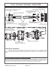
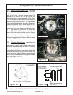
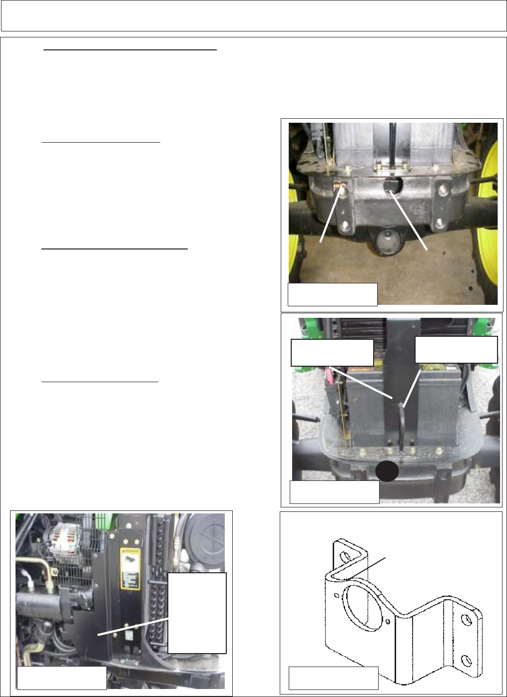
Figure 22
P/N 02979436
Machined Pump
Mount Plate
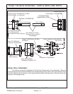
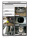
17. Install Pump Drive Shaft. The pump Drive Shaft
has a 7/8" X 13 spline end and a 3/4" w/ 3/16" keyway end
(See Figure 23 & 23A). The 7/8" x 13 spline end goes
toward the engine and fits into the spline hub that was
bolted to the crankshaft (See Figure 13, 13A & 13B). Coat
the splined end of shaft with an anti-sieze compound
before inserting it into the splined hub.
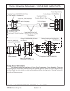
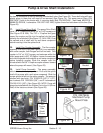
18. Install Flex Coupler Assembly. The flex coupler
assembly P/N 02975188 (See Figure 24) is an assembly
with center coupler, both flanges and bolt nut sets. One
coupler is 3/4" w/ 3/16" keyway and setscrew while the
other (pump side) is 5/8" X 9 Spline. Loosen the setscrew
and coat the keyed shaft end with a anti-seize compound
before installing coupler. Slide the coupler onto the
driveshaft with the 5/8" X 9 spline coupler outward toward
where the pump will mount. (See Figure 25).
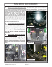
19. Install Pump Assembly. The pump assembly
bolts to the machined pump mount. First coat the spline
shaft of the pump with a anti-seize compound. Slide the
pumps splined shaft into the spline coupler. The pump is
retained with two bolts, P/N 00023100 (3/8" X 1-1/2"),
two Locknuts P/N 00015800 (3/8") and 2 Lockwashers
P/N 00012101 (3/8") (See Figure 26). NOTE: Pump will
always be installed with the Suction Port to the LH (Driver
Side) of the tractor as shown (See Figure 26).
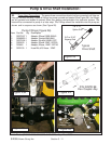
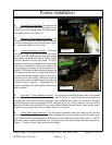
16. Install Machined Pump Mount Plate The machined pump mount plate (P/N 02979436) bolts to
the front of the bolster in the four existing threaded bolt holes (See Figure 22). These bolt holes will have
plastic plugs in them that will need to be removed (See Figure 14). The pump mount Plate (P/N
02979436 ) bolts to the tractor with 4 mounting bolts (Bolt P/N 02975692 -
Hex Head M20-P2.5 X
50MM PL GR10.9
, Lockwasher P/N 02971158 - M20) tighten these four bolts down at this time (See
Figure 25).
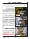
Pump & Drive Shaft Installation:
Bolster
Cover
Hood Latch
Bracket
Battery Hold
Down
Figure 19
Figure 20
Figure 21
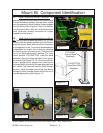
LH
Engine
Side
Shield
Shown
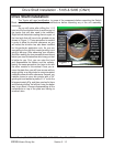
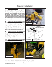
Bolster
Cut Out to allow
driveshaft clearence