


© 2005 Alamo Group Inc.
Section 5 - 9
Switch Blade (JD-5105-5205-5225-5325-5425-5525, Asy. Man) 05/05
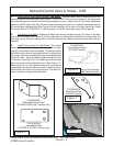
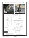
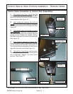
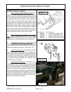
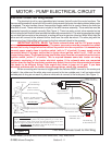
5. Install Electrical Switches. The electric neu-
tral safety switch and the head reversing switch both
mount into the valve mounting bracket (See Figure
22, and Electrical section in this assembly manual).,
Make certain that the battery cables are disconnected
before connecting any electrical connections, this is
to prevent the shorting of any components. Check the
tractors manufactures service /repair manual for any
restrictions or special instructions about connecting
electric components to the tractor.
HydraulicControl Valve & Hoses
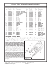
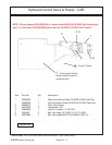
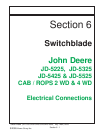
Control Valve & Hoses:
1. The two spool valve assembly shown (See
Figure 21) shows the fittings that are used on the two
spool control valve. Study the drawing. When working
on valve always clean the exterior of the valve and
hoses before disconnecting them. After disconnect-
ing the hoses cap them with clean caps to keep
contamination out of hydraulic system. When disas-
sembling the valve make certain the OD of it and all
work areas are clean, do not use dirty tools or rags that
will leave lint. Only lint free towels (paper or suitable
type) can be used to wipe down the hydraulic system.
If any components need to be held in the valve body
during assembly petroleum jelly can be used.
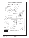
2. When Connecting the hoses to the control
valve follow the directions as shown in the hydraulic
diagram (See Figure 26). Do not connect hoses
backward as this could damage the components.
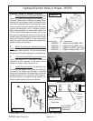
3. The control handle will connect direct to the
valve on ROPS Trctor (See Figure 23), the electric
reversing switch and components also connect to the
valve mount bracket as shown (See Figure 22).
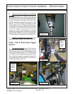
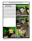
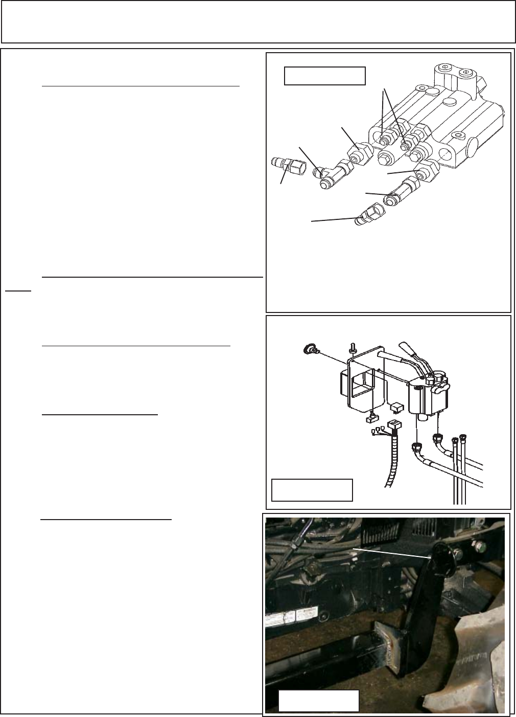
4. Install The Hose Holder. This will bolt on the RH
side of front bolster (See Figure 23). Looking at the
side of the tractor you will see 8 threaded holes, bolt
hose holder in the lower hole in second set back from
front (16 mm Hole) (See Figure 23). All hoses will be
run through sleeving material, this must be done
before they are connected.
Figure 21
Item Part No. Qty. Description
1. 02968850 2 Adapter,Straight 8MB - 6MJ
2. 03200284 2 Adapter,Straight 6MB - 4MJ
3. 02965166 2 Adapter,Tee 6FJX - 6MJ - 6MJ
4. 02982479 2 Adapter, Straight 4MB - 6FJX
1
2
3
4
2
3
4
Figure 22
Figure 23
P/N 02978281
Hose Ring
Weldment