


© 2005 Alamo Group Inc.
Section 3 - 2
Switch Blade (JD-5105-5205-5225-5325- 5425-5525, Asy. Man) 05/05
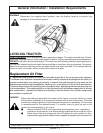
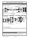
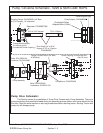
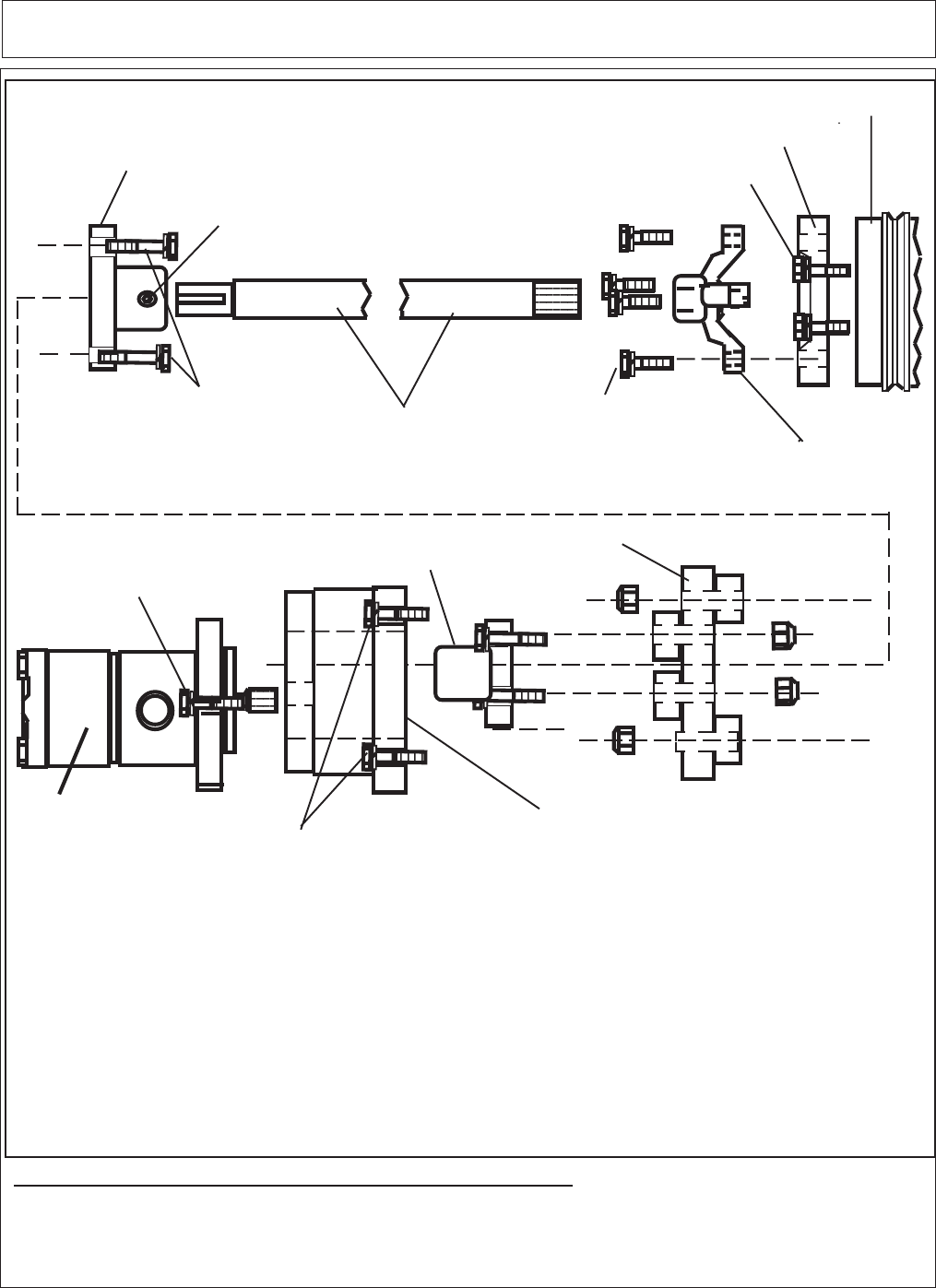
Pump / Driveshaft Schematic - 5425 & 5525
Drive Shaft, 3/4" w/ 3/16"
Keyway X 7/8" w/ 13 spline
Tractor Engine Pulley
Pulley Adapter,
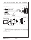
Pump Drive Schematic:
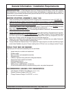
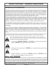
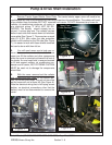
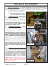
This Section covers the installation of Pump Drive Components, Pump Assembly Some
precautions that must be followed during the Assembly Process before unit is ever started for the first
time.
7/8" X 13 Spline3/4" w/ 3/16" Keyway
Coupling Flange, P/N 0062000 ( 3/4" Bore
w/ 3/16" keyway, 1/4" setscrew )
Flange, P/N 02974359
( 5/8" Bore w/ 9 Spline )
Center Coupling, w/ Nut & Bolt Set
Flange Mounting Bolts
& Locknuts (4 ea.)
Pump Mount,
Pump Assembly
P/N 02973992
Hub, P/N 02702900
P/N 02979436
P/N 02982530
Use Existing Bolt & Lockwasher
From Crankshaft Pulley
( 4 ea.)
Bolts, P/N 02976344
Lockwasher, P/N 00022200
( Included W/ Center Coupling )
Hub
Bolts, P/N 02975692
Lockwasher, P/N 02971158
( Set Of 4 Bolts)
Bolts, P/N 00023100
Lockwasher P/N 00012101
Locknuts, P/N 00015800
Setscrew, P/N 02957080
NOTE: Shown above is the pump - drive component schematic. There are some items from the tractor
that will be reused and some items that are only available as an assembly. The tractor from the
manufacturer has a thin spacer bolter to the crankshaft pulley, remove this spacer and reinstall the spacer
from Alamo Industrial using the same four bolts that mounted the tractor factory spacer.