


© 2005 Alamo Group Inc.
Section 4 - 3
Switch Blade (JD-5105-5205-5225-5325-5425-5525, Asy. Man) 05/05
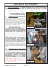
Figure 3
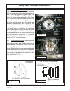
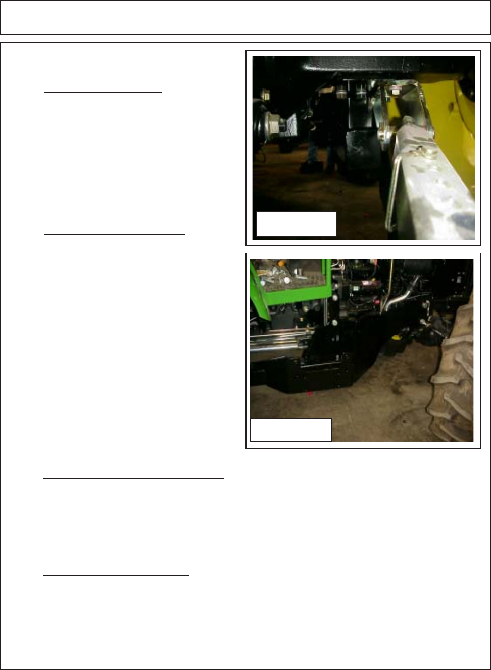
Figure 2
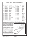
Frame Installation
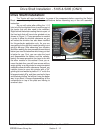
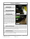
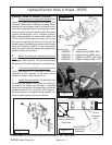
2. Remove RH Side Steps. The steps on the
RH side of the tractor will be removed and not
used so as not to interfere with the clearence of
the mower head. (See Figure 3).
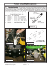
3. Remove 3-Point Stabilizer Bracket The
RH side 3 point stabilizer bracket will be unbolted
from the tractors rear axle housing (see Figure
2). Leave the stabilizer off for now.
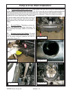
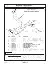
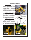
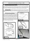
4. Install Frame Rail to Tractor. The frame
rail (Item 1 Figure 1) will be slid under the tractor
on the RH side. Make certain the plastic plugs
have been removed from tractor frame, two at
the front bolster and two mid frame. Do NOT
tighten the frame mounting bolts until all the bolts
have been installed as frame will need to be
moved slightly for alignment as the bolts are in-
stalled. The frame can be installed by balancing
the frame on a floor jack, if using this method it
is recommended two people perform this to pre-
vent the frame from falling. Raise the frame up
to the tractor frame, install the two front bolts and
washers (Item 5 Figure 1). Remember do not
tighten these bolts until all the bolts in frame have
been installed.
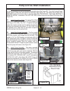
5. Re-Install 3-Point Stabilizer Bracket The three point stabilizer bracket will be reinstalled
under the rear frame at the rear tractor axle. (Item 2 Figure 1). Install frame mounting bolts and
lockwashers, once these four bolts (through 3 point stabilizer and frame rail ) have been installed
all the frame bolts can be tightened. NOTE: the bolts at the rear of the frame are 16 mm and the
bolts at mid frame and front are 20 mm and will have different torque values, check tractor speci-
fications and /or restrictions for the torque of bolts in the holes.
6. Install Sub-Frame Weldment. The Sub frame weldment bolts the frame at the mid way
point (Item 3 Figure 1), There are four bolts, lockwashers and nuts used to install the sub frame.
The mounting holes are designed so sub-frame will only attach one way (See Figure 1). NOTE:
Sub-frame has a cylinder lug welded to it, this lug will be at the bottom and to the rear as shown in
Figure 1. Torque the four sub-frame mounting bolts
(Page Rev 01-23-06)