


© 2005 Alamo Group Inc.
Section 6 - 2
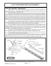
Switch Blade (JD-5105-5205-5225-5325-5425-5525, Asy. Man) 05/05
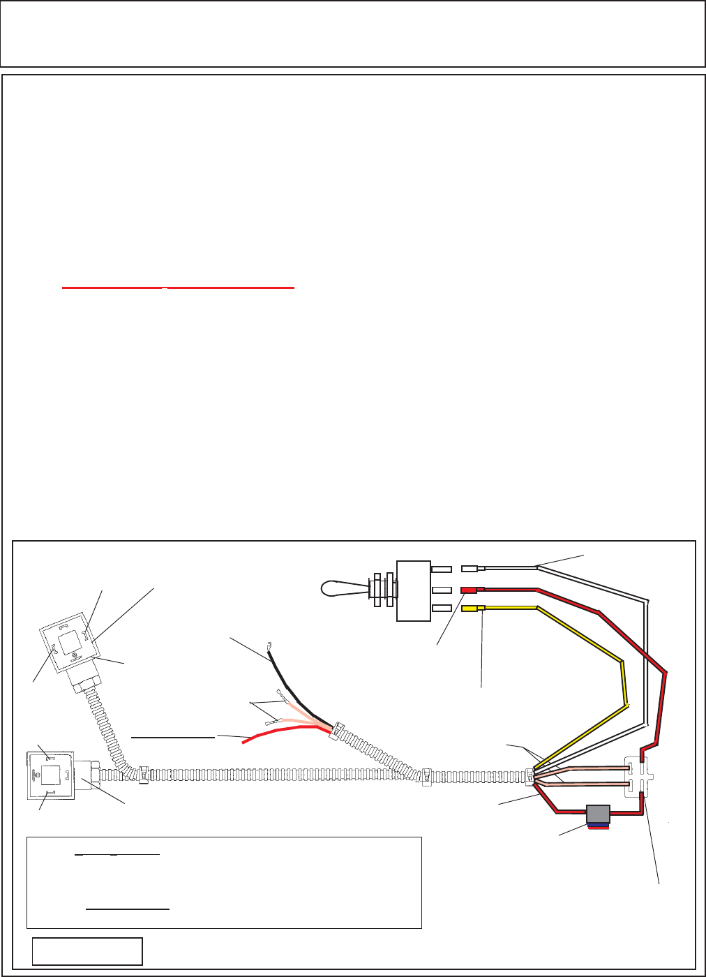
MOTOR - PUMP ELECTRICAL CIRCUIT
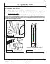
Electrical Circuit: RH Wing Mower
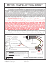
The electrical circuit is a pre-assembled wire harness that will control the motor functions. The
harness will be used with a push pull off/on switch that prevents the tractor from being started when motor
is engaged. The wire harness uses a three position toggle switch that is used to reverse the knife bar
direction of travel. These switches are not part of the wire harness assembly, These switches must be
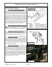
connected correctly to operate correctly (See Figure 1). There is a motor control valve mounted on top
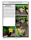
of the hydraulic tank that will have two electrical solenoids connected to it. The wire harness has two plugs
on one end that connects to the solenoids, one plug will have longer wire (also has White Wire) than the
other and will connect to the solenoid further most from the cutter bar mount. The other plug with the
shorter wire (has Yellow Wire) will connect to the first solenoid closet to the operator.
IMPORTANT NOTICE, READ: The Starter solenoid wires and the 12V power supply
wire must be connected to tractor wiring, The power source wire must be connected to a power
source that is only charged when the tractors key switch is in the on position. It is nessasary to
connect power supply close to ignition switch, (with in 3" of switch). If power supply wire is
connected direct to a power source that is charge when ignition switch is off, it will run the
tractor battery down. The Solenoid wires (two Brown wires) must be connected close the tractor
ignition switch, (within 3" of switch). This is required because some later tractor are using
electronic monitoring of the tractor electrical system. If the solenoid wires are connected
further down the line the monitoring system may detect this circuit as disconnected and cause
the tractor to do different things, from engine shut down to jump out of gear. If you have
electrical problems with the tractor doing strange things, check this connection.
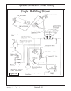
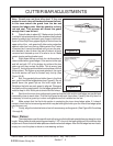
When connecting wire harness to toggle switch the red wire MUST connect to the center post
of switch, the yellow and the white wire must connect to the two outside post, it will not mater which
outside post as long as one each of yellow or white wire is connect to the outer post (See Figure 1).
Figure 1
This Wire Harness Used for RH Wing
Yellow #16 Wire
1
2
3
1
2
3
- Black #16 Wire
White #16
Wire
+ Red #16 Wire
(12 Volt Supply)
Brown # 12 Butt Connectors
Wire to Starter Solenoid
- Black #16 Wire
(Common Ground)
- Black #16 Wire
4 Terminal Plug
for Push Pull Switch
Fuse Holder with 10
AMP Inline Fuse
Red #16 Wire
Brown #12 Wire
Use Gaskets to
Seal Both Plugs
Front Solenoid Plug
Rear Solenoid Plug
NOTE: + Red # 16 Wire (12 Volt Supply) Connect to Key Switch Connection
(within 3" of switch) that is positive only when ignition key is in “ON” Posi-
tion. If connected to direct power supply and push pull switch is left on when
tractor is stopped and parked it will run down the tractor battery.
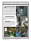
Push Pull Switch, Wire Harness plug will only fit one way on push
pull switch to prevent it being connected wrong.
Yellow #16 Wire
(Spade Connector)
White #16 Wire
(Spade Connector)
Red #16 Wire
(Spade Connector)