


OPERATION
Eagle 20 03/09 Operation Section 4-17
© 2009 Alamo Group Inc.
OPERATION
“B
o
tt
om
i
ng
O
u
t”
Ch
ec
k
P
roce
d
ure
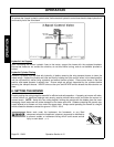
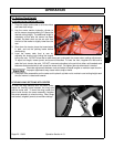
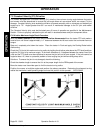
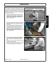
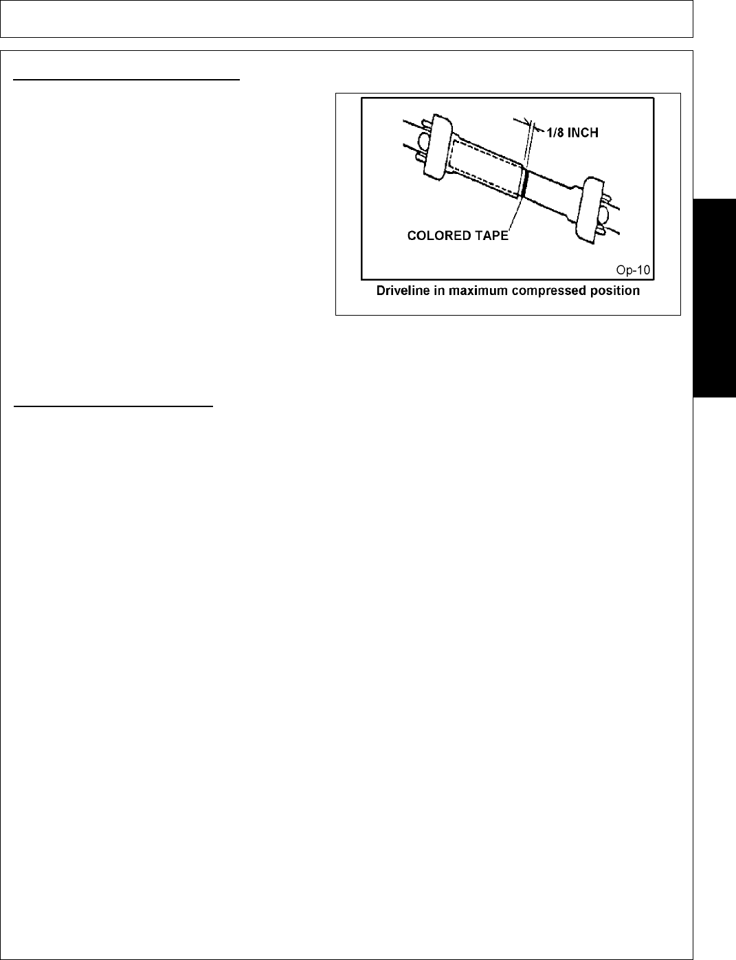
• Disconnect driveline from the tractor and slide
the profiles together until fully compressed.
• Place a mark on the inner shield 1/8” from the
end of the outer shield.
• Reattach the driveline to the PTO Shaft.
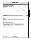
• Lift Type - With the PTO NOT TURNING, raise
and lower the mower and watch shaft move-
ment.
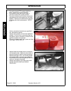
Pull Type - With the PTO NOT TURNING, drive
the tractor and mower through the sharpest turn
possible and watch shaft movement. With the
PTO NOT TURNING, drive the tractor and
mower through the most severe terrain condi-
tions expected and watch shaft movement.
• Raise the mower and watch the driveline as it
approaches the mark. If the distance between the mark and the end of the outer shield tube becomes less
than 2” at any point, contact your local dealer or tech service for proper directions. OPS-R-0004_B
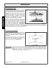
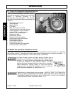
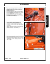
Engagement Check Procedure
• With the driveline attached, position the mower to the point where the telescoping driveline is at its maximum
extension. Completely shut down the tractor and secure in position.
• Mark the inner driveline shield 1/8” from the end of the outer shield.
• Disconnect the driveline from the tractor and separate the two driveline halves.
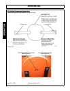
• Measure the distance from the mark to the end of the inner profile. This length is the amount the driveline profiles were
engaged.
• If the engaged length is less than 6”, the shaft is considered too short and should be replaced with a longer shaft.
Consult an authorized dealer to purchase the required driveline length.
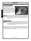
NOTE: If the driveline cannot be shortened and still maintain the required profile engagement, the operator must be made
aware of terrain conditions and avoid situations which pose a potential problem to avoid damaging the driveline or move
drawbar to 16” or 20” position for required clearance. OPS-R-0005_O