


SSB Transmitters
169
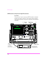
NOTE: Test set up and cabling for this test are critical. RF feedback into the
Transmitter audio input may cause the displayed waveform to be distorted.
Use caution to carefully bypass input lines at the microphone connector when
performing this test.
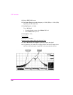
17. Verify that the distortion products (smaller signals to either side of the side-
band signals) do not exceed the Transmitter’s specification.
If incorrect, repeat step 4 using reduced modulation levels until the distor-
tion products meet specified limits.
NOTE: If the distortion product specification is expressed as a percentage, it must be
converted to dB for use in this measurement. A rating of 10% distortion
products corresponds to a reduction of 20 dB, 5% is 26 dB, and 3% is 30 dB.
If the distortion product specification is unknown, use 30 dB.
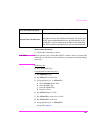
On the Test Set:
18. Select TX Power W.
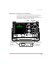
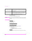
19. Press the REF SET key.
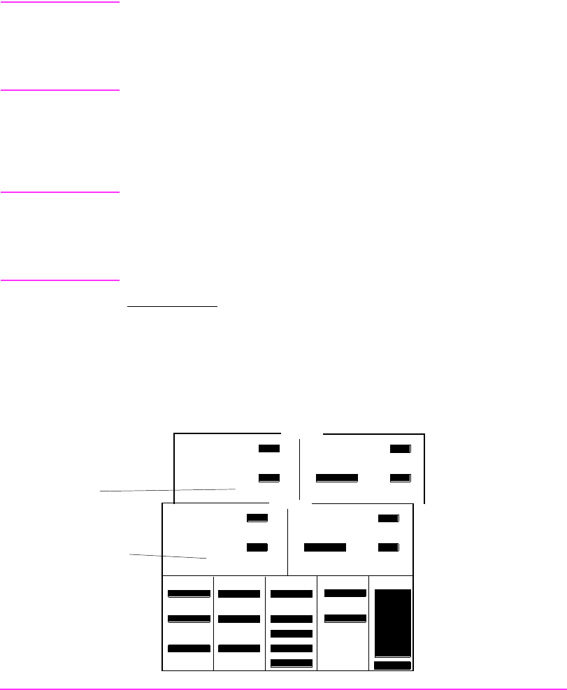
Measurement results are displayed as TX Power.
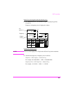
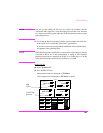
Carrier Suppression is displayed as TX Power as shown.
TX TEST
AC Level
TX Frequency
TX Power
AF Freq kHz
V
W
MHz
28.311451
16.3 6.11381
0.2371
Carrier Sup-
pression
SSB
Power
Tune Mode
To Screen
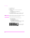
TX TEST
AC Level
Auto/Manual
TX Frequency
TX Power
Tune Freq
28.311000
MHz
IF Filter
15 kHz
Input Port
RF in/Ant
AF Anl In
SSB Demod
Filter 1
50Hz HPF
Filter 2
15kHz LPF
De-Emphasis
750 us/Off
Detector
Pk+-Max
Ext TX Key
On/Off
TX Pwr Zero
Zero
AFGen1 Lvl
50.0
mV
AF Freq
RF GEN
RF ANL
AF ANL
SCOPE
SPEC ANL
ENCODER
DECODER
RADIO INT
More
AFGen1 Freq
1.0000
kHz
kHz
V
dB
MHz
28.301370
-42.94 6.11381
0.2371