25
Agilent 6800 series setup
• Connect the ac source output to the ac input of
the equipment under test.
• Use the computer to develop a 1024 point array
representing a cycle of voltage amplitude data.
• Use the TRACe:DEFine command to name the
waveform CLASS 1 and allocate non-volatile
storage space.
• Use the TRACe:DATa command to send the 1024
point array to the ac power source/analyzer.
• Set the Shape to List mode.
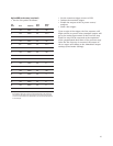
• Set the List points as follows:
List Point Shape Dwell Time
1 Sine 120 s
2 CLASS1 120 s
3 Sine 120 s
• Set the List to sequence automatically.
• Set the transient trigger source to BUS.
• Initiate the transient trigger.
• Enable the output.
• Send a Bus trigger.
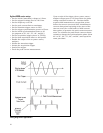
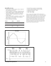
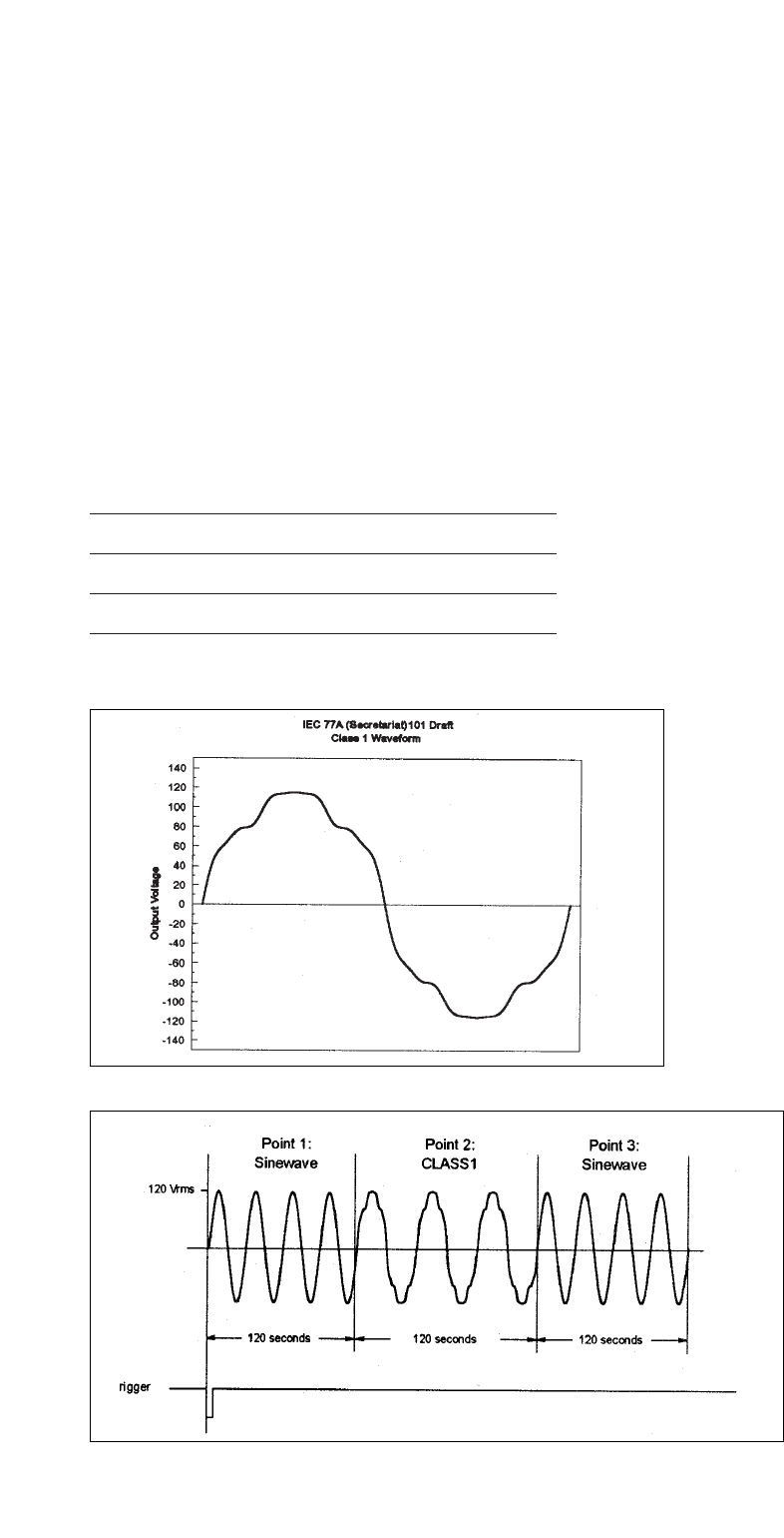
Upon receipt of the trigger, the first List step is
executed and the output is set to a 120 Vrms, 60 Hz
sinewave. After 120 seconds, the ac power source/
analyzer automatically executes the second List
step. The output will remain at the CLASS 1 test
level for 120 seconds and then will execute the
third List step. After the entire List is executed,
the output of the ac power source/analyzer will
return to the Fixed mode levels.
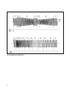
Timing Diagram for Application #5


