


11
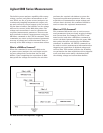
Overview of application
The ability of a switching power supply to main-
tain its output voltage setting in the presence of
typical ac line disturbances is critical to its end-
use. If the end-use of the power supply is installa-
tion into a computer, for example, sensitivity to
ac line variations can result in unexpected loss of
critical data and system downtime. To simulate
these common ac line voltage variations, an ampli-
tude controlled ac voltage can be applied to the
ac input of the power supply.
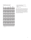
For this example, the power supply requires a
single phase ac source set to a nominal line voltage
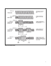
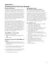
of 120 Vrms and frequency of 60 Hz. To test the
power supply under worst case conditions, a volt-
age dropout to 0 Vrms should occur between 80°
and 110° (i.e. a duration of 0.001389 seconds) on
the voltage waveform. This is a steadystate test,
which means that the dropout occurs after the
ac input of the power supply under test has settled
from all non-repetitive inrush conditions that
typically occur at power-up.
Agilent 6800 series features used
• RMS voltage in Pulse mode
• Trigger synchronization to the output voltage
phase
• Trigger delay
Advantages/benefits of the Agilent 6800 series
solution
• By using the trigger phase synchronization
capability, the timing of the dropout is accurate
and repeatable.
• By using the transient capability, the computer
is not devoted to sequencing the output.
• By using the trigger delay, it is assured that the
power supply is in steadystate operation.
• One command initiates the test.
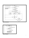
Implementation details
How the 6800 series implements the dropout
The computer sends a trigger to the ac power
source/analyzer with a programmable delay of
5 seconds to ensure that the ac input to the power
supply under test is in a steadystate condition.
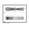
The ac source outputs a low distortion 120 Vrms
sinewave during the trigger delay and allows the
power supply to stabilize into steadystate opera-
tion. After 5 seconds, the ac power source/analyzer
responds to the trigger and drops the output volt-
age to 0 Vrms starting at 80° of one output voltage
cycle and lasting for 0.001389 seconds.
Agilent 6800 series setup
• Connect the ac source output to the ac input
of the power supply under test.
• Set the output waveform to sine.
• Set the rms voltage to Pulse mode.
• Set the initial (immediate) voltage to 120 Vrms.
• Set the triggered voltage level to 0 Vrms.
• Set the frequency to 60 Hz.
• Set the Pulse count to 1.
• Set the Pulse width to 0.001389 seconds
(the width of 30° of phase dropout for a 60 Hz
sinewave).
• Set the transient trigger source to BUS.
• Set the transient trigger source synchronization
to PHASE.
• Set the phase synchronization to 80°.
• Set the trigger delay to 5 seconds.
• Initiate the transient trigger system.
• Enable the output of the ac power source/
analyzer.
• Send a bus trigger.
Application 1:
Simulating AC Line Sub-Cycle Dropouts