


14
Overview of application
U.S. Military Standard 704D (September 30, 1980)
establishes the requirements of electrical power
transfer between the aircraft or ground support
electrical system, and the electronic equipment
utilizing this power on board the aircraft. When
testing to this standard, electrical aircraft equip-
ment must be subjected to voltage and frequency
transients that can occur under normal operation,
emergency power operation, and during power
source transfers.
The “pass” criteria for aircraft equipment is depend-
ent upon the specification of the equipment under
test. In general, the intent of the test is that:
• the equipment is permitted a degradation or
loss of function unless required otherwise by
its specifications
• the equipment is not permitted to produce a
damaging or unsafe condition
• the equipment must automatically recover full
specified performance when normal ac power
characteristics are restored
For this example, the equipment under test has
a single phase ac input with 115 Vrms and 400 Hz
requirements. The device is tested under ac voltage
transients initially, and then under frequency tran-
sient conditions. These transients are as follows:
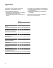
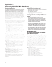
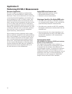
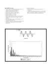
At 400 Hz:
Voltage Test 1: 180 Vpk (127 Vrms) for 10 ms, and
then slew to 124 Vpk (88 Vrms) at 800 Vpk
(566 Vrms) per second.
Voltage Test 2: 80 Vpk (57 Vrms) for 10 ms, and
then slew to 108 Vpk (76 Vrms) at 400 Vpk
(283 Vrms) per second.
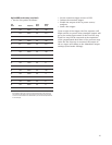
At 115 Vrms:
Frequency Test 1: 425 Hz for 1 s, 420 Hz for 4 s,
410 Hz for 5 s, and 407 Hz for 4 s.
Frequency Test 2: 375 Hz for 1 s, 380 Hz for 4 s,
390 Hz for 5 s, and 393 Hz for 4 s.
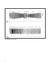
In this example, the voltage and frequency tran-
sients will be executed as an integrated test
sequence.
Agilent 6800 series features used
• RMS voltage and frequency control in List mode
• RMS voltage slew control
• List dwell time control
• Triggering system to execute the List
Advantages/benefits of the Agilent 6800 series
solution
• The List capability allows the ac power
source/analyzer outputs to sequence through
each RMS voltage and frequency setting with
accurate timing according to the standard and
without controller intervention.
• By using the programmable RMS voltage slew
control, the RMS voltage level excursions can
be faithfully reproduced as per the standard.
• The List settings for MIL-STD-704D are stored
in non-volatile memory, so the test need only
be set up once and then executed as needed.
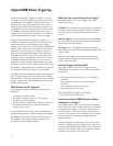
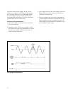
Implementation details
How the 6800 series implements MIL-STD-704D RMS
voltage and frequency transients
The computer sets up List sequence, then ac power
source/analyzer is sent a bus trigger. Upon receipt
of the trigger, the ac power source/analyzer’s out-
put is set according to the voltage, voltage slew,
and frequency values of the first List point. The
output will remain at the first List point setting
until the dwell time for that List point expires. The
unit will then sequence through each successive
List point paced by the respective dwell times until
the List is completed. Upon completion of the List,
the output will return to the immediate settings.
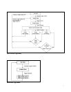
Agilent 6800 series setup
• Connect the ac source output to the ac input
of the equipment under test.
• Set the rms voltage to 115 Vrms.
• Set the frequency to 400 Hz.
• Set the rms voltage to List mode.
• Set the rms voltage slew to List mode.
• Set the frequency to List mode.
• Set the List to sequence automatically.
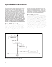
Application 2:
Generating MIL-STD-704D Waveforms