


24
Overview of application
The creation of user-defined waveforms is useful
for simulating ac line disturbances that are unique
to the operational environment of the device being
tested, and then measuring that device’s suscepti-
bility to the disturbance. This is the fundamental
objective of environmental test standards that per-
tain to the ac line. A specific example is the draft
for IEC 77A (Secretariat) 101 draft (dated 10/15/93),
which defines the test and measurement methods
for evaluating electronic and electrical equipment
immunity to voltage harmonics and inter-harmon-
ics on the ac line. Upon subjecting the equipment
to the voltage harmonics, it must recover to its full
operative capabilities to meet the “pass” criteria
of this draft.
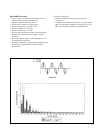
For this example, a waveform with harmonic volt-
age content as defined by the IEC 77A (Secretariat)
101 draft (dated 10/15/93) will be created, stored,
and generated by the ac power source/analyzer.
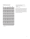
Harmonic Voltage Levels (for 120 Vrms)
Harmonic Number Class 1 Class 2
3 9.6 V 7.2 V
5 10.8 V 9.6 V
7 6 V 8.4 V
11 2.4 V 8.4 V
13 2.4 V 7.2 V
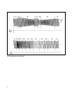
The equipment under test used for this example
has an ac input rating of 120 Vrms, 60 Hz, and
5 Arms. The waveform generated will comply with
the Class 1 harmonic combination (as currently
proposed) shown above. This draft specifies that
the equipment under test must be subjected to
the harmonic waveform of either Class for 2 min-
utes, succeeded by 2 minutes of the fundamental
(120 Vrms sinewave) waveform.
Agilent 6800 series features used
• Non-volatile, user-defined (arbitrary) waveform
creation/storage
• rms voltage programming
• Frequency programming
• Waveform shape transient generation
• List transient mode
Advantages/benefits of the Agilent 6800 series
solution
The user-defined waveform is stored in non-
volatile memory, eliminating the need for con-
stant re-creation and making it easy to recall
the waveform as the test is needed. A List of out-
put waveforms can be generated by combining
built-in and user-defined waveforms, simplifying
complex test sequences. The user-defined wave-
form can be recalled as if it was one of the stan-
dard output shapes (such as sine and square
waveforms) and can be used in all modes where
the FUNCtion:SHAPe command is valid.
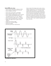
Implementation details
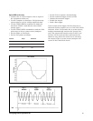
How the 6800 series implements user-defined waveforms
The computer is used to generate an array of
1024 voltage amplitude points that represent one
cycle of the 77A (Secretariat) 101 Class 1 wave-
form. This data is sent to the ac source as a named
(CLASS 1) user-defined waveform and is stored in
a non-volatile memory location. The List mode of
the ac power source/analyzer is used to sequence
through the appropriate output settings at 2-minute
intervals as per the draft. The programmed param-
eters for each List point are shape (waveform) and
dwell time. The rms voltage and frequency output
settings remain in Fixed mode. The first List point
is the fundamental waveform (120 Vrms sinewave
at 60 Hz) and will be output upon receipt of a tran-
sient trigger for 2 minutes. The CLASS 1 waveform
will be output for 2 minutes as part of the second
List point. After this 2-minute test, the fundamen-
tal waveform will be output again as part of the
final List point.
Application 5:
Generating User-Defined Waveforms