


21
Overview of application
Switch mode power supplies are commonly used
in many electronic products. These power supplies
typically have input capacitors that cause high
levels of peak inrush current to be drawn as they
charge from the rectified line at turn-on. The peak
amplitude of the inrush current varies with the
turn-on phase of the ac voltage cycle. Usually, the
highest peak inrush currents occur near the peak
(90°) of the voltage cycle. Characterization of
inrush current versus turn-on phase allows for
determination of worst case inrush current condi-
tions, which must be determined to properly select
fuses and circuit breakers, to uncover component
stresses, and to determine if a product will pro-
duce ac line disturbances that interact with other
equipment connected to the branch circuit.
For this example, the equipment under test
requires an ac line voltage of 120 Vrms at 60 Hz.
Agilent 6800 series features used
• RMS voltage and frequency control
• Peak current measurement
• Pre-event current data capture
• Trigger synchronization to the output voltage
phase
• Measurement and waveform generation
synchronization
• High crest factor
Advantages/benefits of the Agilent 6800 series
solution
The 6800 series provides a “One-Box” Solution for
measurement and waveform generation and elimi-
nates the worry of synchronizing separate instru-
ments. The ability to turn-on relative to the output
voltage phase allows worst case inrush characteri-
zation, which results in a more reliable product.
Implementation details
How the 6800 series implements peak inrush current
measurements
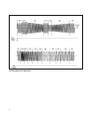
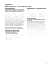
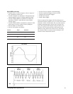
The RMS voltage is programmed to Step mode
to generate a turn-on condition from 0 Vrms to
120 Vrms. The turn-on is synchronized to the
phase of the output voltage. The current measure-
ment is programmed to occur at turn-on with
10 milliseconds of pre-event data to ensure that
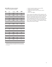
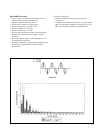
the full inrush event is captured. To characterize
the inrush current of the unit under test, the turn-
on phase is initially set to 40° for the first peak
inrush current measurement and is then increased
at 10° increments up to 90° for succeeding peak
inrush current measurements. Between tests, the
input capacitors of the unit under test are allowed
to fully discharge for proper characterization.
Application 4:
Performing Inrush Current Measurements