26
15
MAINTENANCE INSTRUCTIONS (continued) SAFETY SIGNS
W ARNING!
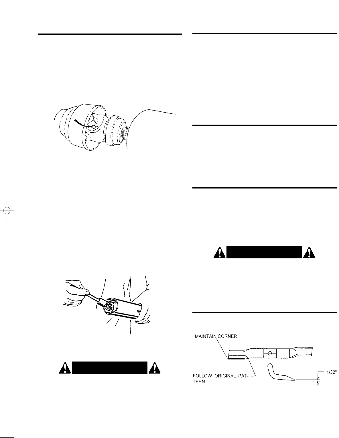
When attaching the driveline yoke to the tractor
PTO shaft, it is important that the spring activated
locking collar turns freely and that the locking pin is
seated on the PTO shaft groove. A loose yoke could
slip off and result in personal injury or damage to the
mower.
W ARNING!
Avoid personal injury! Always support or block the
mower when servicing the blades, carrier or any
other component on the underside of the deck.
The metal telescoping drive tubes inside the plastic
shield tubes must be lubricated before each use. See
figure 11.
Disconnect the driveline from the tractor and pull halves
apart (do not disconnect the driveline that is attached to
the mower gearbox). Insert grease into drive tube and
spread it evenly. Reconnect the two driveline halves
together. Reconnect the driveline to the tractor PTO,
raise and lower the mower several times so that the
grease just applied spreads over the entire working area
of the drive tubes.
DRIVELINE LUBRICATION
Grease fittings are located on the cross and bearing kit
assemblies of both U-joints. U-joints should be greased
after every 8 hours of operation. See figure 10 for the
location of the grease fittings. Do not force grease
through the needle bearing cup assemblies.
BLADE SPINDLE LUBRICATION
Blade spindles must be lubricated after every 8 hours of
operation. Access the lubrication fittings through the
holes in the belt guards. Each spindle is supplied with a
grease fitting on top, and it must be lubricated sufficiently
so that a small amount of grease escapes through the
bleed hole on their underside. Do not force large
amounts of grease on the spindles, as it may get on the
drive belts.
BLADE SERVICING
Use only correct specified blades on your mower. They
are manufactured of special heat-treated alloy steel.
Substitute blades may not meet specifications and may
fail in a hazardous manner, which could cause injury.
BLADE SHARPENING
To maintain a proper blade balance, always sharpen
both ends of the blade equally. Follow the sharpening
pattern as shown on figure 12. Do not sharpen the
blades to a razor edge, but leave a
1
/
32
” blunt edge.
Never sharpen the back side of the blades.
BLADE REMOVAL
Hold the end of the blade using heavy leather gloves
and remove the left hand threaded bolt.
Figure 10
Figure 11
Figure 12
ITEM 1 – Part No. 101103
ITEM 2 – Part No. 101173
DANGER
THROWN OBJECT HAZARD
To prevent serious injury or death:
• Do not operate unless all guards
are installed and in good condition.
• Stop blade rotation if bystanders
come within several hundred feet.
M600
ITEM 8 – Part No. 101101
WARNING
OPERATE THIS MACHINE AT
540 RPM
TRACTOR PTO SPEED ONLY
Overspeeding PTO may cause component
failure with resulting injury.
ITG 100
DANGER
ROTATING DRIVELINE HAZARD
To prevent serious injury or death from
rotating driveline:
• Keep all guards in place when operating.
• Operate only at 540 RPM.
• Keep hands, feet, hair and clothing away
from moving parts.
SW104
Replace Safety Signs
if Damaged or Missing!
26 / 15 - FM001 12/6/00 3:40 PM Page 1


