


22
19
ASSEMBLY INSTRUCTIONS
The mower will attach to most tractors with a Category
I, 3 pt. hitch system and a 540 RPM PTO. Do not
exceed horsepower recommendations.
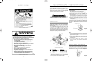
DANGER!
Operating with PTO speed over 540 RPM can cause
excessive vibration and mower failure, which can
result in serious injury or even death.
W ARNING!
A loose shaft could slip off and result in personal
injury or damage to the mower. When attaching the
driveline yoke to the tractor PTO shaft, it is important
that the spring activated twist collar turns freely and
that the locking pin is seated on the PTO shaft groove.
W ARNING!
Before operating the mower check to make sure the
driveline will not bottom out or become disengaged.
See figure 6.
CAUTION!
Always use personal protection devices such as
eye and ear protection during assembly.
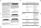
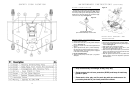
A-FRAME AT TACHMENT
Attach the rear brace bars (1) to the lugs on the rear of
the deck with M12 bolt, washer, lockwasher, and locknut.
Attach the A-Frame bars (2) to the lugs on the front of the
deck with M12 bolt, washer, lockwasher, and locknut.
Attach the other end of the A-Frame bars (2) at the top
and between the rear brace bars and top link (3) with
M12 bolt, (2 each) washer, (3 each) spacer, lockwasher,
and locknut. See figure 1.
DRIVELINE TO MOWER
GEARBOX ATTACHMENT
1. Grab and turn the yoke collar of the driveline end to be
attached to the gearbox. Note: Make sure that you
connect the driveline end with the male shield
tube to the mower.
2. Slide the yoke with the collar turned onto the mower’s
gearbox input shaft. Note: Make sure that the plas-
tic protective cone is mounted on the gearbox.
3. Move yoke back and forth until its locking pin has
engaged on the gearbox input shaft groove.
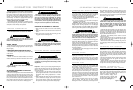
3 PT. HITCH AT TACHMENT
Remove bolt from hitch point location and assemble as
shown in figure 2.
Figure 1
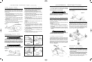
Figure 5
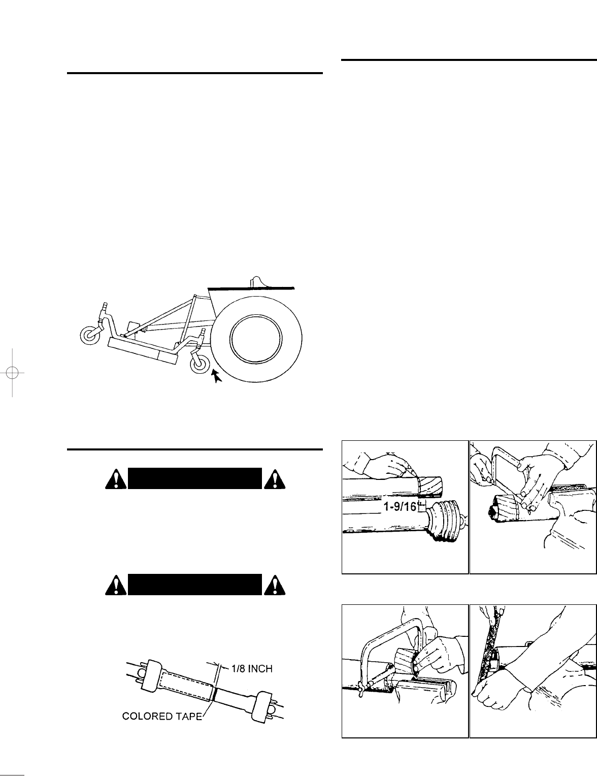
Front Gauge Wheel Clearance
Figure A Figure B
Figure C Figure D
Figure 6
Driveline in maximum compressed position
Figure 2
CASTER WHEEL ATTACHMENT
Figure 3
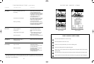
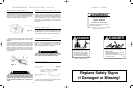
DEALER SET-UP INSTRUCTIONS
Assembly of this mower is the responsibility of the
dealer. The mower should be delivered to the owner
completely assembled, lubricated and adjusted for
normal cutting conditions.
Set-up mower as received from the factory with these
instructions.
• Remove mower from crate.
• Complete assembly of factory pre-assembled hitch.
• Refer to parts lists and exploded view drawings for
more details.
• To complete assembly, it will be easier if components
are aligned and assembled loosely before tightening
hardware.
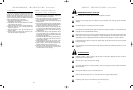
ADJUSTING DRIVELINE LENGTH
1. Slide the driveline together until it “bottoms out.”
2. Apply colored tape to the inner plastic shield tube
1
/
8
”
from the end of the outer shield tube.
3. Reconnect the driveline to the tractor PTO shaft.
4. Raise the mower to full transport position or until the
driveline just hits the deck at front.
5. If the distance between colored tape and outer shield
tube is 1
9
/
16
” or less, the metal drive tubes
should be shortened per figure A.
6. Shorten the male and female plastic shield tubes
equally. See figure B.
7. The metal drive tubes also have to be shortened in
the same length as the plastic shield tubes. See
figure C.
8. Round off all sharp edges and remove burrs. See
figure D.
9. Apply grease to the metal drive tubes.
10. There should always be a minimum of 1
9
/
16
” clear-
ance between the male and female drive and shield
tubes when the driveline is operated in its shortest
working position.
11. Lower the mower to the lowest position possible and
check the distance of the colored tape to the end of
the outer shield tube.
12. Driveline tube engagement or overlapping must
always exceed 12”.
13. If tubes do not overlap by 12” or more, consult with
your dealer to obtain a longer driveline.
FRONT GAUGE WHEEL
INTERFERENCE CHECK
Do not operate the mower until this interference check
has been performed. If you use the mower with a differ-
ent tractor, you must perform the check for that particular
mounting again.
1. Raise the mower with the tractor hydraulic system to
the maximum height of lift.
2. Pivot both of the mower front gauge wheels forward
and check that there is clearance between the gauge
wheels and the tractor’s rear tires.
3. If there is interference, lower the mower to the ground
and move hitch to the extended position (see assem-
bly chapter).
4. Move the tractor tires inward to obtain clearance or
lower the mower until clearance exists.
5. Set the 3-point quadrant stop so the mower cannot be
raised beyond the set point. See figure 5.
DRIVELINE LENGTH CHECK
PROCEDURE
OPERATION INSTRUCTIONS (continued)
Some mowers will be supplied with all four wheels fully
assembled. However, for models that do require
assembly, please follow these instructions. Install two
3
/
4
”
spacers on each fork and wheel assembly shaft. Insert
fork shaft into axle arm weldment. Additionally install two
3
/
4
” and two
3
/
8
” spacers on each axle shaft and retain
using the snapper pins supplied. See figure 3.
22 / 19 - FM001 12/6/00 3:24 PM Page 1