


Dealer Service 19
51642 (Rev. 11/9/2007)
DEALER SERVICE
The information in this section is written for dealer ser-
vice personnel. The repair described herein requires
special skills and tools. If your shop is not properly
equipped or your mechanics are not properly trained in
this type of repair, you may be time and money ahead
to replace complete assemblies.
Keep hands, feet, hair, and clothing away from
equipment while engine is running. Stay clear of all
moving parts.
Before performing any service or maintenance,
lower mower to ground or block securely, turn off
tractor engine, remove key, set parking brake, and
remove belt from tractor PTO sheave.
■ Before working underneath, raise mower to
highest position and block securely. Blocking up
prevents mower dropping from hydraulic leak
down, hydraulic system failures, or mechanical
component failures.
Keep all persons away from operator control
area while performing adjustments, service, or
maintenance.
Always wear relatively tight and belted clothing
to avoid getting caught in moving parts. Wear
sturdy, rough-soled work shoes and protective
equipment for eyes, hair, hands, hearing, and head;
and respirator or filter mask where appropriate.
BLADE SPINDLE REPAIR
Spindle repair requires special skills and tools. If your
shop is not properly equipped or your mechanics are
not trained in this type of repair, you may be time and
money ahead to use a new spindle assembly.
Periodically inspect blade spindles by grasping pulley,
moving from side to side and up and down. If end play
or wobble is noted, replace or repair.
Rotate spindle. If it feels rough (indicating bad bear-
ings), replace or repair. Bearing adjustment is main-
tained by drilling a hole through the sleeve and spindle
shaft and inserting a roll pin.
For reference, grease fitting is in top of housing.
Permatex® Aviation Form-A-Gasket or equivalent is
recommended as a sealant.
Removal
Remove blade from spindle.
Remove belt from pulleys.
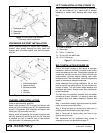
Disassemble split taper bushing (located on top of pul-
ley) by removing the two bolts and inserting them into
the threaded holes of bushing flange. Tighten them
alternately to remove split taper bushing. Remove key
and pulley.
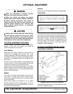
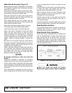
Disassembly (Figure 13)
Remove bolts attaching spindle to mower frame and
remove spindle.
Drive roll pin out of sleeve and shaft.
Place spindle assembly in press and press the shaft
down through housing.
Remove seals from housing.
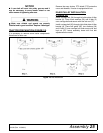
Remove bearing cups from housing by placing a punch
in slots provided and driving out. Alternate punch posi-
tions from side to side. Take care to prevent housing
damage.
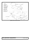
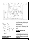
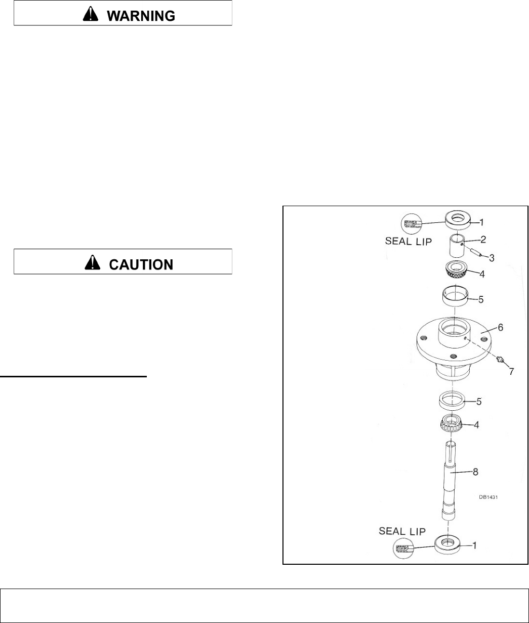
Figure 13. Blade Spindle Assembly
1. Seal
2. Sleeve
3. Roll pin
4. Bearing
5. Cup
6. Spindle housing
7. Grease fitting
8. Spindle shaft