


10 Operation
51642 (Rev. 11/9/2007)
OPERATION
The designed and tested safety of this machine
depends on it being operated within the limitations as
explained in this manual. Be familiar with and follow all
safety rules in the manual, on the mower and on the
tractor.
The safe operation of this mower is the responsibility of
the operator, who must be properly trained. The opera-
tor should be familiar with the equipment and all safety
practices before starting operation. Read the safety
information on page 5 through page 9.
This mower is designed for lawn and grass mowing
and is equipped with suction-type blades for best
results. Optional blades are available for varying soil
and grass types. Refer to the Optional Equipment sec-
tion for additional information.
Recommended tractor ground speed for most condi-
tions is from 2 to 5 mph. Always operate tractor PTO at
1000 rpm.
Never allow children or untrained persons to
operate equipment.
Keep bystanders away from equipment.
Before performing any service or maintenance,
lower mower to ground or block securely, turn off
tractor engine, remove key, set parking brake, and
remove belt from tractor PTO sheave.
Keep all persons away from operator control
area while performing adjustments, service, or
maintenance.
Always wear relatively tight and belted clothing
to avoid getting caught in moving parts. Wear
sturdy, rough-soled work shoes and protective
equipment for eyes, hair, hands, hearing, and head;
and respirator or filter mask where appropriate.
Stop power unit and equipment immediately
upon striking an obstruction. Turn off engine,
remove key, inspect, and repair any damage before
resuming operation.
CUTTING HEIGHT ADJUSTMENT
Mower cutting height may be raised, lowered and
maintained using tractor hydraulics and lift chains.
Optional caster wheels may be used to maintain cutting
height. Proper lift chain adjustment is essential for both
cutting height control methods.
NOTICE
■ Tractor upper stop of hydraulic control lever
must be set to prevent any part of mower from
coming closer than 1/4" to the tractor or mower lift
bracket when mower is in the fully raised position.
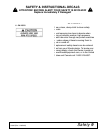
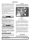
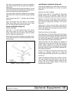
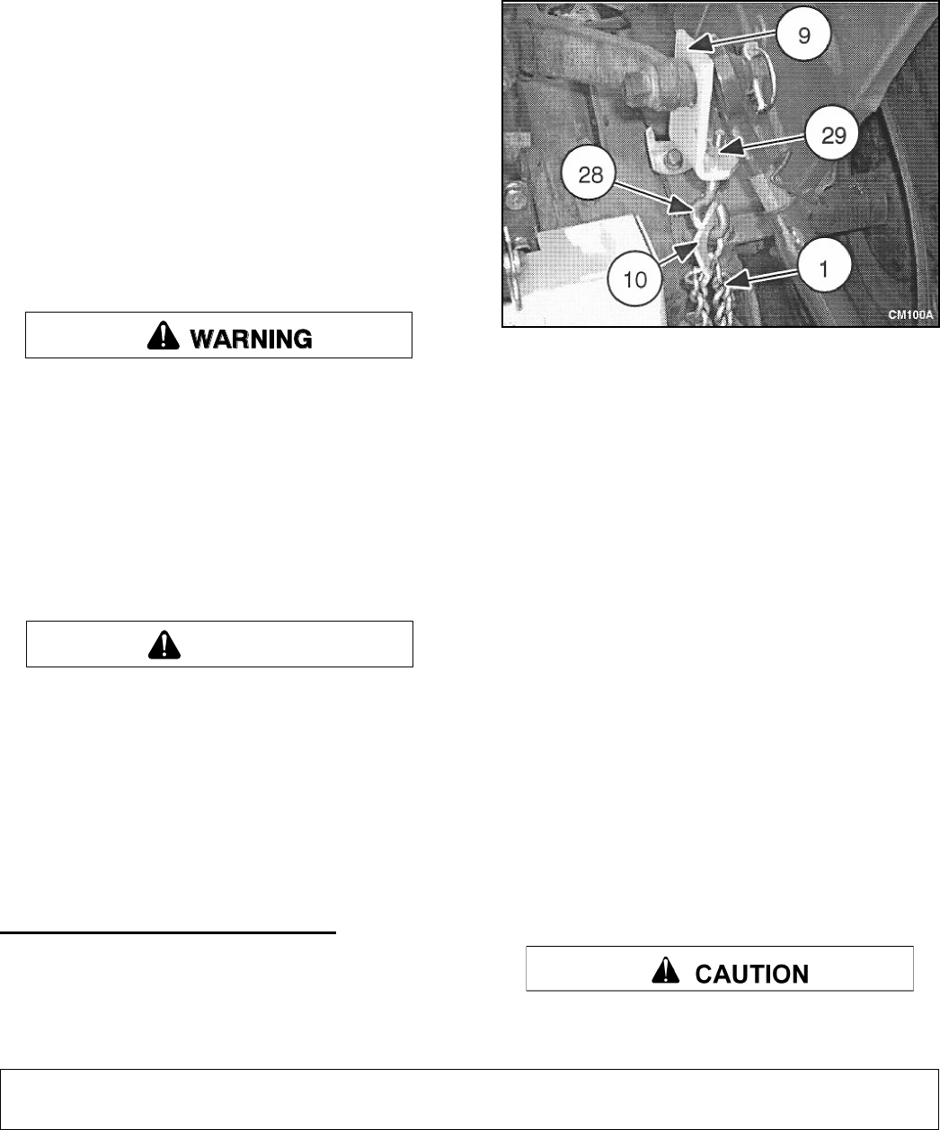
1. Hook Chain
9. Lift Angle
10. Lift Lug
28. Eyebolt
29. 3/8" Hex Nut
Figure 1. Cutting Height Adjustment
Attach lift angle (9) to tractor upper lift rock shaft arm.
Run a 3/8" hex nut (29) halfway down eyebolt (28),
then assemble to lift angle with a second 3/8" hex nut.
Do not tighten hex nuts until final adjustments are
made.
Hook chain (1) into slotted lift lug (10). Slip slotted lift
lug over the end of open-end eye bolt. Repeat for
opposite side, making sure chains are untwisted and
that the same chain link is inserted into the slotted lift
lug.
Slowly raise mower to determine if correct chain link
was selected which allows for sufficient lift. Once the
correct chain link is selected, raise mower until no com-
ponent is closer than 1/4" to tractor. Set the upper stop
of the tractor hydraulic control lever at this point.
With the lift height set, side to side leveling adjustment
can be made by adjusting the 3/8" hex nuts on each lift
angle (9). Tighten hex nuts when adjustment is com-
plete.
Failure to properly adjust hydraulic control lever
stops may result in damage to tractor and mower.
CAUTION