


31
Maintenance Instructions
REPLACING/REPAIRING/
ADJUSTMENTS
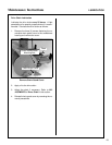
Scraper Blade
Inspect the scraper blade for wear or damage be-
fore each use. The blade is hardened and if the
gauge wheels (or skid shoes) are properly adjusted,
the blade should give a reasonable amount of ser-
vice before replacement. The blade should be re-
placed before it has worn down to the point where
the blade mount on the housing is dragging and
wearing.
IMPORTANT: Continued operation with a worn out
scraper blade and/or improperly adjusted gauge
wheels will result in severe damage to the lower por-
tion of the snowblower housing.
The scraper blade is replaced by removing seven
(7) 1/4-20 x 3/4 carriage bolts and nuts.
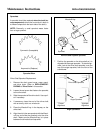
Flexible Coupling Spider
Inspect the flexible coupling spider after every 25
hours of operation. If the elastomeric media shows
signs of wear, cracking or deterioration, the spider
should be replaced. Refer to Gearbox Replace-
ment in this section for removing and replacing the
spider.
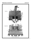
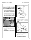
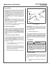
U-Joint Shear Pin (After S/N 99-1042)
In case of sudden stoppage of the auger, the PTO
U-joint connection to the gearbox has a shear pin to
provide shock load protection to the drivetrain.
When the PTO pin has sheared, use the following
procedure to replace it:
1. Remove the gearbox cover. Two (2) bolts (one
on each side) fasten the cover.
2. Rotate U-joint on shaft to align the shear pin
hole with the hole (and shear pin fragment) in
the shaft. Use a punch to drive the remaining
portion of the old shear pin out.
3. Install new shear pin and secure with cotter pin.
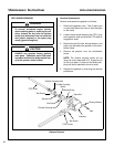
PTO Shear Pin
IMPORTANT: Use only Walker P/N 8067-10 shear
pins for replacement to provide proper shock protec-
tion -- these pins are hardened to shear under a spe-
cific amount of load.
4. Reinstall the gearbox cover.
Before operating the blower after the shear pin has
been replaced, inspect the auger flighting and pad-
dle blades for damage. Also inspect the gearbox
and chain drive for any damage. Make sure the au-
ger turns smoothly and freely before resuming oper-
ation.
ADJUSTMENTS
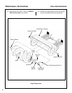
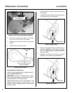
Drive Chain Tension
The drive chain should have 1/4 to 1/2 in. (6 to 13
mm) of slack at midspan. Remove the chain guard
cover to check slack. Adjust the drive chain as fol-
lows:
1. Loosen the chain tension block mounting nut
and bolt.
WARNING
DO NOT attempt to make any adjust-
ments with the tractor engine running.
Disengage the PTO clutch, stop the en-
gine, and remove the ignition key. Wait
for all movement to stop before getting
off the seat.
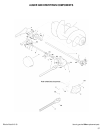
Cotter Pin
U-Joint
Tube Assembly
Shear Pin
Split Spring Pin
U-Joint
Shaft Assembly