


Assembly Instructions
12
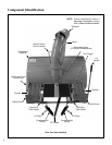
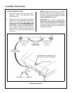
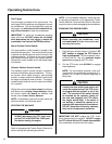
Align PTO Shaft and PTO Coupler
(shown before engaging snowblower mounting
tubes with tractor support arms)
b. Slide snowblower assembly onto tractor.
Reaching under the tractor, pull the ring
back on the PTO quick coupler, slide the
coupler onto the tractor spline shaft, and
release the coupler ring.
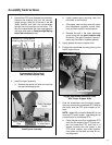
IMPORTANT: To prevent damage to the machine,
make sure the PTO quick coupler is securely locked
on the tractor, with the locking balls fully seated in
the groove and the ring in the full forward position
(refer to the Coupler Ring “Locked” Position pho-
to). After installation, pull on the shaft to check for
security.
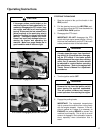
Installing PTO Quick Coupler
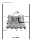
Coupler Ring “Locked” Position
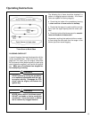
8. Insert the hitch pins in the ends of the tractor
support arms.
9. Pull the lift handle back, press the foot trigger,
and push the snowblower lift handle forward
against the spring pressure into the DOWN (for-
ward) position. Attach each of the lift chains to
the lift brackets with a 5/16-18 x 1-1/4 in. bolt
and an ESNA nut.
NOTE: Use a bungee cord or strap to secure lift
handle in forward position while connecting lift
chains to tractor.
10. Reinstall the PTO cover.
Attach Lift Chains to Lift Brackets
Pilot End
PTO Shaft
Arrows
Spline Connection
To Tractor
PTO Coupler
Pull Back Spring-Loaded
Coupler Ring
Spring-Loaded Coupler Ring
In Full Forward Position
Lift Chain
Lift Bracket
Hitch Pin