


Assembly Instructions
11
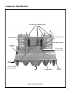
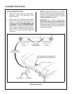
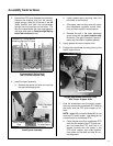
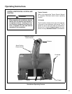
3. Remove the PTO cover (between the footrests).
Remove the shipping wire from the counter-
weight springs, place the lift handle in the UP
(back) position, and hook the counterweight
springs onto the hook tabs on the frame. The
tabs are located below the right angle gearbox
and drive shaft (refer to Counterweight Spring
Hook Tab Locations photo).
Counterweight Spring Hook
Tab Locations (bottom view)
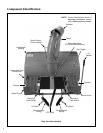
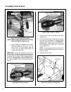
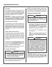
4. Install the spout assembly.
a. Remove the center bolt and nut mounting
the spout discharge guard.
Install Spout Assembly
b. Lightly grease spout mounting neck and
pivot area on the housing.
c. Slide spout onto housing neck with spout
point backwards (opposite normal direc-
tion) and then rotate to normal position.
d. Reinstall the bolt in the spout discharge
guard along with the spout rotation stop
as shown in the parts illustration (spout ro-
tation stop included in hardware packet).
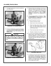
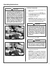
5. Lightly grease the tractor support arms.
6. Engage the snowblower mounting tubes on the
tractor support arms.
Engage Snowblower Mounting Tubes
with Tractor Support Arms
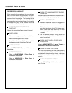
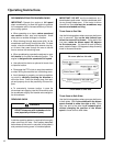
7. Slide the snowblower onto the tractor support
arms and connect the snowblower PTO shaft to
the tractor with the PTO quick coupler as fol-
lows:
NOTE: Model MS and earlier Model MC do not
have the PTO quick coupler. Use sliding joint to
connect tractor to snowblower PTO.
a. Place the pilot end of the snowblower PTO
shaft into the socket of the PTO quick cou-
pler and rotate the PTO shaft until it is
aligned correctly with the socket in the
PTO quick coupler, then slide together.
Use arrows on the shaft and tube for cor-
rect alignment.
Remove PTO Cover Before
Attaching Springs To Frame
Spring Hook Tabs
Remove This Bolt
To Install Spout
Spout Rotation
Stop
Spout Discharge
Guard
Support Arms
Mounting Tubes