


43
Maintenance Instructions
REPLACING/REPAIRING
ADJUSTMENTS
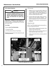
7. Install the new gearbox on the spline coupling of
the drive shaft. Establish correct timing of the
blade drive gearboxes by setting flats on the
output shaft at 90 degrees when connecting the
gearbox(es) to the spline coupling. Make sure
the timing is correct before proceeding with as-
sembly.
8. Reinstall the four (4) bolts mounting the gear-
box to the connector tube but do not tighten
them at this time; leave connector tube bolts fin-
ger-tight.
9. Position the gear drive assembly on the deck
and install the 3/8-16 bolts mounting the entire
assembly. Leave the mount bolts finger-tight.
10. Torque all the connector tube bolts to 80 in-lb
(9 N
⋅m); then tighten the deck mount bolts.
NOTE: This fastener tightening sequence
aligns the gearbox assembly with the deck hous-
ing and eliminates the possibility of mounting the
unitized assembly in a bind.
11. Fill gearbox assembly with oil. Refer to Mower
Deck Gearbox Lubrication in this section for
instructions.
12. Reassemble remaining items onto deck to com-
plete installation. After installing blades, check
that the blade timing is correct by moving the
blades through one (1) complete revolution.
Make sure blade tips pass clear of each other.
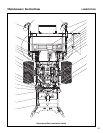
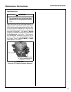
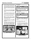
Mower Deck Gearboxes
(Shown with Gearbox Cover Removed for Clarity)
ADJUSTMENTS
Blade Clutch (PTO)
Clutch Disengagement/Brake Action
The blade brake is activated by linkage to the clutch
pulley mechanism. The brake is designed to stop
the blades within five (5) seconds after disengaging
the clutch.
Use the following procedure to check and adjust
clutch disengagement and brake action:
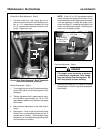
1. Evenly adjust the nuts on the end of the brake
band to achieve 1/4" of travel of the PTO gear-
box assembly between the engaged and the
disengaged position (refer to PTO Gearbox En-
gagement Photo).
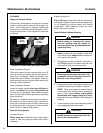
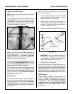
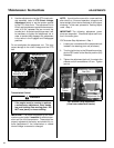
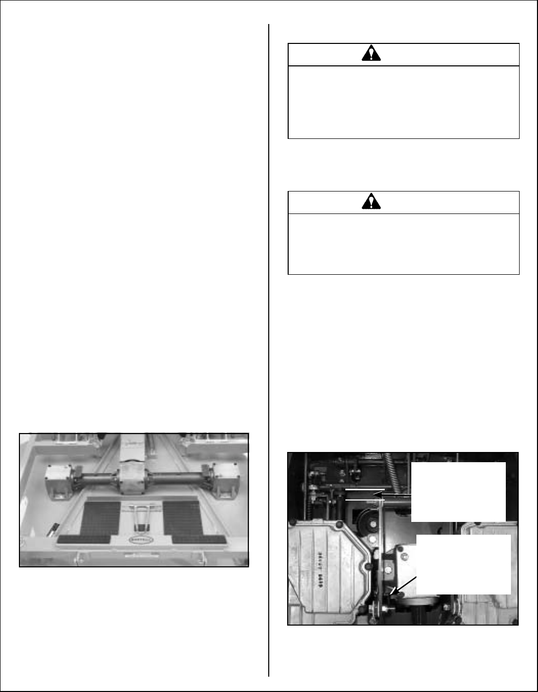
PTO Gearbox Engagement
(view from underside of tractor)
DANGER
If the engine must be running to perform
a maintenance adjustment, keep hands,
feet, and clothing from moving parts. DO
NOT wear jewelry or loose clothing.
WARNING
It is important to check and maintain blade
brake action for safe operation of the ma-
chine.
Brake Band
Adjustment Nuts
Located at Front
of Assembly
(Not Visible)
Assembly Should
Move 1/4" Between
Engaged and
Disengaged
Position