


Assembly Instructions
16
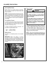
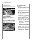
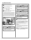
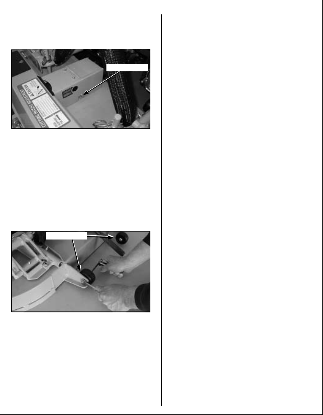
PTO Shaft Guard Installation
Position the shaft guard as shown and mount with
two 1/4-20 x 1/2 in. bolts.
PTO Shaft Guard Installation
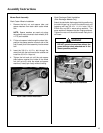
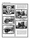
Tilt-Up Roller Wheel Installation
NOTE: A 2-1/2" diameter tilt-up roller wheel
(P/N 9772) is required for decks installed on the
walk-behind.
Mount the two (2) tilt-up roller wheels on the brack-
ets on the rear skirt of the deck housing using the
P/N 8490 axle bolt, 3/8 in. wave spring washer and
3/8-16 in. Whiz locknut. Tighten the axle bolt until
the wheel rolls freely, but is not loose.
Tilt-Up Roller Wheel Installation
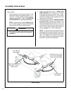
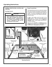
Mower Deck Installation on Tractor
Deck Installation
1. Lightly grease each deck support arm (2) on the
tractor. Refer to Mower Deck Installation
photo for location of deck support arm.
2. Engage the deck carrier frame tube sockets on
the tractor support arms. Slide the deck onto
the support arms.
NOTE: When installing the DSD52 Mower
deck, make sure to retract the dolly wheel after
mounting the deck on the tractor.
3. Install the hitch pin through the hole on the end
of each support arm to lock the deck in place
(refer to Counterweight Spring Receptacle
Assembly photos). Two (2) hitch pins are
included in the owner’s packet of materials.
4. Connect the mower deck PTO drive shaft
assembly to the tractor with the splined quick
disconnect coupler. This coupler simplifies
shaft alignment and installation.
a. Use the arrows on the shaft and tube to
align and slide the PTO quick coupler onto
the deck splined shaft.
b. Reaching under the tractor, pull the ring
back on the coupler, slide onto the spline
shaft on the tractor, and release the ring.
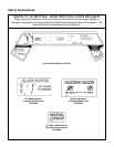
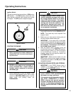
IMPORTANT: To prevent damage to the
mower, make sure the PTO shaft assembly is
securely locked on the tractor, with the locking
balls fully seated in the groove and the ring in the
full forward position (refer to the Coupler Ring
“Locked” Position photo). After installation,
pull on the shaft to check for security.
Attach Guard
Roller Wheels