


Assembly Instructions
2
2
CHECK GEAR AXLE OIL LEVEL
Refer to Gear Axle Lubrication in Maintenance In-
structions.
INSPECT FOUR (4) DRIVE BELTS
Engine PTO Drive, Jackshaft Drive, Hydrostatic
Ground Drive, and GHS Blower Drive (if equipped).
CHECK HYDROSTATIC TRANSMISSION OIL
LEVEL
Refer to LUBRICATION for
Checking Hydrostatic
Transmission Fluid
Level
in Maintenance Instruc-
tions.
CHECK BATTERY ELECTROLYTE LEVEL
Refer to CHECKING/SERVICING the Battery in
Maintenance Instructions.
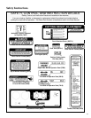
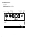
CHECK FUNCTIONS OF INSTRUMENT PANEL
AND WARNING HORN
Turn the ignition key to the RUN position. Voltmeter,
Oil Pressure Light, and Warning Horn should all op-
erate, indicating normal function.
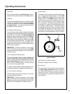
CHECK TIRE PRESSURE
Deck Caster Wheel = 20 PSI (137 kPa)
Drive = 15 PSI (103 kPa)
Rear = 20 PSI (137 kPa)
CHECK AND CLEAN GRASS BUILDUP UN-
DERNEATH MOWER DECK (and inside GHS
blower, if equipped)
Refer to CLEANING the GHS Blower in Mainte-
nance Instructions for blower cleaning information.
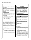
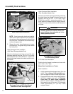
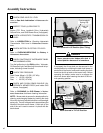
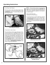
NOTE: Mower deck is secured in raised position for
cleaning and changing blades by hooking the deck
lift rod into the body bracket below the counterweight
spring clip. The rod is hinged and is stowed along the
footrest of the deck carrier frame. A hitch pin on the
end of the rod is used to secure it in place with the
deck raised.
Deck Secured in UP Position (Non-Tilting)
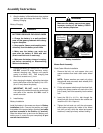
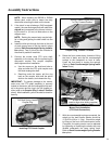
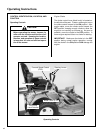
If equipped, the tilt-up deck can be secured in the
raised position by unlocking the deck lock levers on
each side of the carrier frame and inserting the deck
hook into the tilt-up latch on the tractor body. Before
operating the tractor, make sure to re-engage the
deck lock levers after lowering the deck to the nor-
mal operating position.
Deck Secured in TILT-UP Position
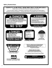
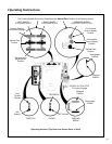
DANGER
Never operate cutter blades with deck in
raised position because it is hazardous.
Body
Bracket
Counterweight
Spring Clip
Deck Lift
Rod
Deck Lock Lever
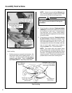
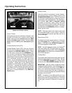
Tilt-Up Latch
Tilt-Up Latch
Tilt-Up Hook
on Deck