


Assembly Instructions
2
0
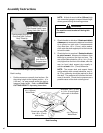
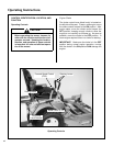
Deck Counterweight Spring Installation
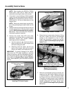
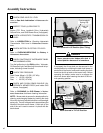
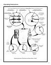
Deck Leveling
1. Position mower on a smooth, level surface. Set
the cutting height to the highest position - 4 in.
(102 mm) - for easy access under the deck to
measure blade height. Refer to ADJUSTING
CUTTING HEIGHT in Operating Instructions.
NOTE: A block of wood cut 4 in. (102 mm) high
is a convenient gauge to measure blade height
above ground during the leveling process.
2. Check the side-to-side level. Rotate each blade
sideways and measure the distance from blade
tip to ground on each side. If measurements
vary more than 1/8 in. (3 mm), add a washer
shim under the deck support pins on the low side
to level the deck.
3. Check the front-to-rear level. Rotate the blades
to point forward. Measure the distance from
blade tip to ground on the front and rear. The
rear of the blade should be 1/8 to 1/4 in. (3 to 6
mm) higher than the front of the blade; shim the
rear (or front) deck support pins equally to
achieve at least 1/8 in. (3 mm) difference.
NOTE: The mower deck and support frame
are jig welded; within normal tolerances, very lit-
tle, if any, shimming should be required to level
the deck. Tire pressure will influence the level-
ness of the deck. Check the tire pressure as a
possible cause of the deck not being level.
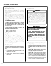
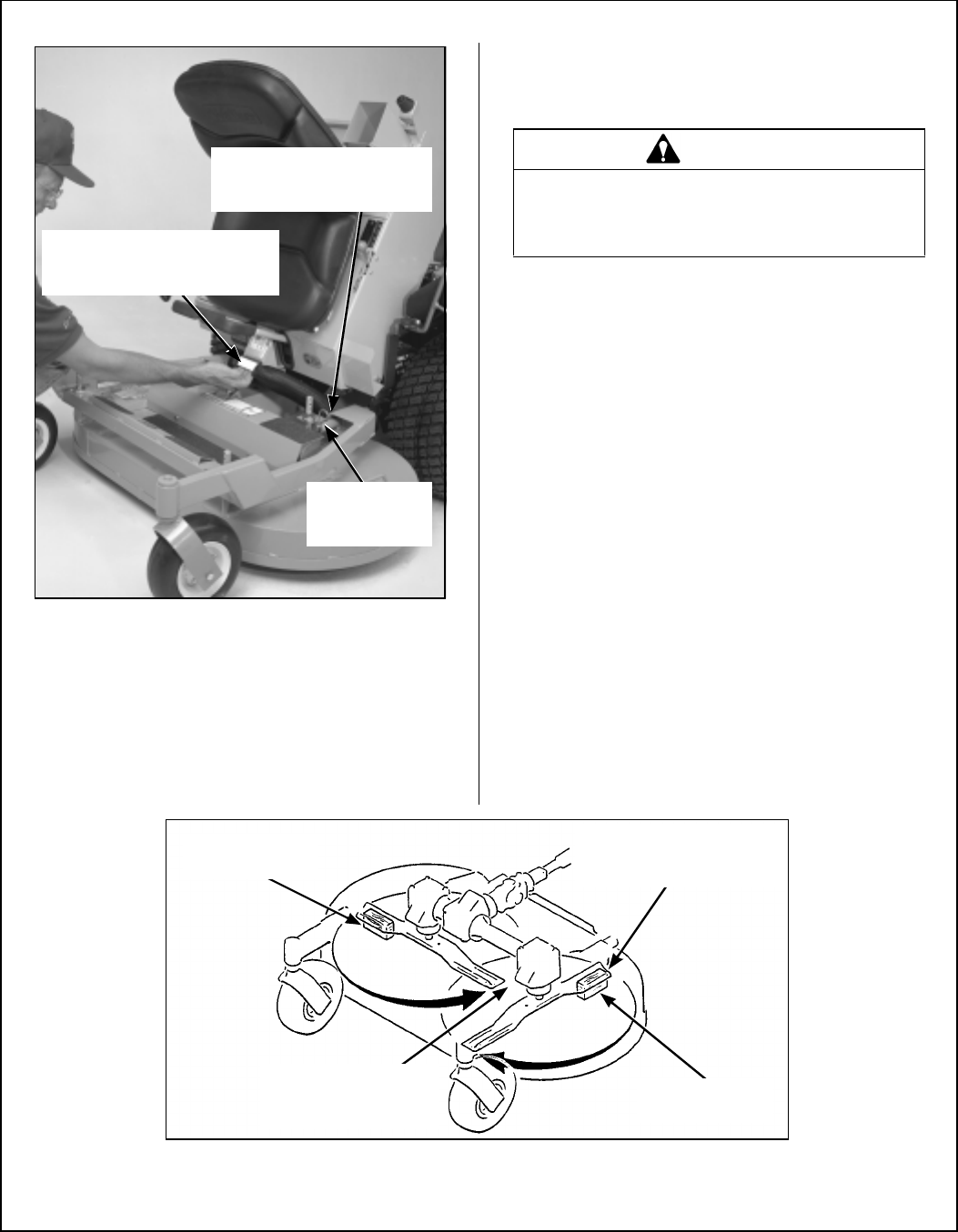
Hitch Pins
Lock Deck On
Support Arms
Counterweight Springs Clip
Onto Body With Forward
Body Tilted Up
Spring Tension Adjustment
Nut Located Under Lower
Spring Hook (Not Visible)
WARNING
The machine must be shut off during this
procedure.
Should be 1/8 in. (3 mm)
to 1/4 in. (6 mm) higher
at the rear of the blade
4 in. (102 mm)
Wood Block
4 in. (102 mm)
Wood Block
Should not vary more
than 1/8 in. (3 mm)
side-to-side
Deck Leveling