


Assembly Instructions
1
9
NOTE: When installing the DSD52 or DSD62
Mower deck, make sure to retract the dolly
wheel after mounting the deck on the tractor.
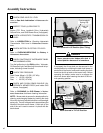
3. If the deck is rear discharge (GHS equipped
model), the rear discharge chute will need to be
aligned and connected to the blower inlet dur-
ing the last 2 in. (51 mm) of slide action on the
support arms.
NOTE: Raising the mower body may be help-
ful in fitting and guiding the deck chute into the
blower.
4. Install the hitch pin through the hole on the end
of each support arm to lock the deck in place
(refer to Deck Counterweight Spring Installa-
tion photo). Two (2) hitch pins are included in
the owner’s packet of materials.
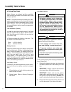
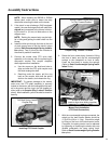
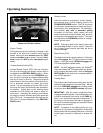
5. Connect the mower deck PTO drive shaft
assembly to the tractor with the splined quick
disconnect coupler. This coupler simplifies
shaft alignment and installation.
a. Use the arrows on the shaft and tube to
align and slide the PTO quick coupler onto
the deck rectangular shaft.
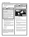
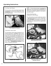
b. Reaching under the tractor, pull the ring
back on the coupler, slide onto the spline
shaft on the tractor, and release the ring.
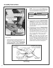
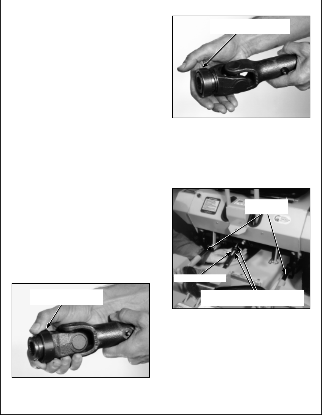
IMPORTANT: To prevent damage to the mower,
make sure the PTO shaft assembly is securely
locked on the tractor, with the locking balls fully seat-
ed in the groove and the ring in the full forward po-
sition (refer to the Coupler Ring “Locked” Position
photo). After installation, pull on the shaft to check for
security.
Installing PTO Quick Coupler
Coupler Ring “Locked” Position
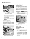
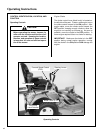
6. Raise the front mower body (instead of lifting
the front of deck) and clip the counterweight
springs to the receptacle on front of body.
Lower the front body to tension the springs.
(Refer to Deck Counterweight Spring Instal-
lation Photo.)
Mower Deck Installation
(PTO Shaft Connection)
7. With the counterweight springs connected, the
weight on the deck caster wheels should be
15 to 25 Ib (6.8 to 11.3 kg). Check this weight
by lifting on the front of the deck carrier frame.
If required, the spring tension can be adjusted
by tightening or loosening the elastic stop nuts
located underneath the lower spring hook.
Refer to Deck Counterweight Spring Installa-
tion photo.
Pull Back Spring-Loaded
Coupler Ring
Spring-Loaded Coupler Ring
In Fully Forward Position
Grease Deck
Support Arms
PTO Connection
Arrows on Shaft and Tube
(used to align when sliding together)