


6
OPERATING INSTRUCTIONS
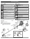
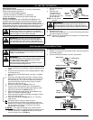
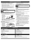
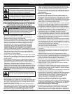
HOLDING THE TRIMMER
Before operating the unit, stand in the operating position (Fig. 15).
Check for the following:
• The operator is wearing
eye protection and
proper clothing
• With a slightly-bent right
arm, the operator’s right
hand is holding the
shaft grip
• The operator’s left arm
is straight, the left hand
holding the handle
• The unit is at waist level
• The cutting attachment
is parallel to the ground
and easily contacts the grass without the need to bend over
TIPS FOR BEST TRIMMING RESULTS
• For best trimming results, operate unit at full throttle.
• Keep the cutting attachment parallel to the ground.
• Do not force the cutting attachment. Allow the tip of the line to do
the cutting, especially along walls. Cutting with more than the tip
will reduce cutting efficiency and may overload the engine.
• Cut grass over 8 inches (200 mm) by working from top to bottom
in small increments to avoid premature line wear or engine drag.
• Cut from right to left.
• Slowly move the trimmer into and out of the cutting area at the
desired height. Move either in a forward-backward or side-to-side
motion. Cutting shorter lengths produces the best results.
• Trim only when grass and weeds are dry.
• The life of your cutting line is dependent upon:
- Proper adherence of explained trimming techniques
- What vegetation is cut
- Where vegetation is cut
For example, the line will wear faster when trimming against a
foundation wall as opposed to trimming around a tree. It is normal
for some line breakage to occur from regular use.
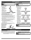
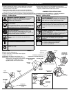
DECORATIVE TRIMMING
Decorative trimming is
accomplished by removing
all vegetation around trees,
posts, fences and more.
Rotate the whole unit so
that the cutting attachment
is at a 30° angle to the
ground (Fig. 16).
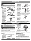
FIXED LINE INSTALLATION
Always use original equipment manufacturer 0.105 inch (2.667 mm)
replacement line. Lines other than those specified may make the
engine overheat or fail.
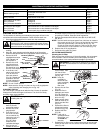
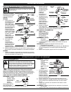
To install the trimming line:
1. Insert each end of the
replacement line into
the holes on either
side of retention hook
(Fig. 17).
2. Push the ends
through until they
stick out of the sides
of the head (Fig. 18).
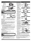
3. Pull the ends
through making sure
that the ends are of
equal length and the
middle of the line is
centered between
the insertion holes
(Fig. 19).
4. If the ends are not of
equal length, push
the longer end back
through the head
part way and pull the
shorter end to
compensate. Repeat
until both ends are
the same length.
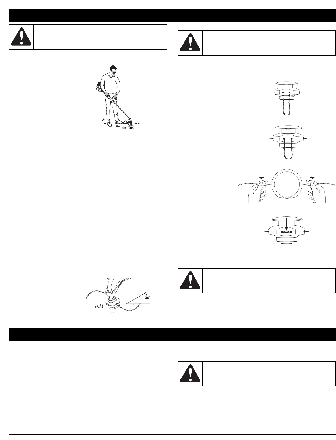
5. Push the trimmer
line until it lies flat
against the cutting
head (Fig. 20).
Make sure the two
lengths of cutting
line are of equal length. If they are not, adjust until they are.
Fig. 15
Fig. 16
Fig. 17
WARNING:
Always wear eye, hearing, foot and body
protection to reduce the risk of injury when operating
this unit.
WARNING:
Never use metal-reinforced line, wire,
chain, or rope. These can break off and become
dangerous projectiles.
Fig. 18
Fig. 20
Fig. 19
WARNING:
A
lways use the correct line length when
installing trimming line on the unit. If the two lengths of
cutting line are not of equal length, the unit may develop a
vibration.
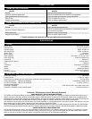
MAINTENANCE AND REPAIR INSTRUCTIONS
MAINTENANCE SCHEDULE
Perform these required maintenance procedures at the frequency stated in
the table. These procedures should also be a part of any seasonal tune-up.
NOTE: Some maintenance procedures may require special tools or
skills. If you are unsure about these procedures take your
unit to any non-road engine repair establishment, individual
or authorized service dealer.
NOTE:
Maintenance, replacement, or repair of the emission control
devices and system may be performed by any non-road engine
repair establishment, individual or authorized service dealer.
WARNING:
To prevent serious injury, never perform
maintenance or repairs with unit running. Always service
and repair a cool unit. Disconnect the spark plug wire to
ensure that the unit cannot start.