


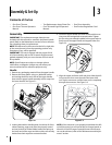
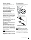
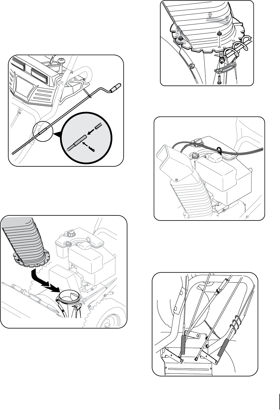
Chute Directional Control
Remove the internal cotter pin from the upper chute
crank. Slide the upper chute crank into the sleeve on the
lower chute crank.
Align the hole in the upper chute crank with the hole
in the sleeve (If necessary, use a pair of pliers to assist
in aligning holes). Insert the internal cotter pin through
the holes to secure the chute crank. See Figure 3-4.
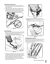
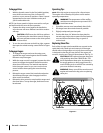
Chute Assembly
Remove lock nuts and screws securing one of the flange
keepers to the chute assembly. Loosen the fasteners of
the other two flange keepers. See Figure 3-5.
Place chute assembly onto chute base as shown in Figure
3-5. Make sure that the chute notches engage with the
spiral end of chute directional control, and the two flange
keepers are beneath the flange on the chute base.
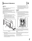
Secure flange keeper removed earlier with lock nuts
and screws. Tighten down nuts securing the other two
flange keepers. See Figure 3-6.
1.
2.
1.
2.
3.
Figure 3-4
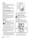
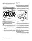
Check that the chute cables are properly routed
through the cable guide on top of engine shroud. See
Figure 3-7.
Headlamp Wire Harness
If not already done, wrap the wire of the head lamp wire
harness down the right handle until the wire can be
plugged into the engine alternator wire connector down
on the engine. See Figure 3-8.
4.
Figure 3-5
Figure 3-6
Figure 3-7
Figure 3-8
a
b
7sectiOn 3 — asseMbly & set-up