


Section 2: Assembly
9
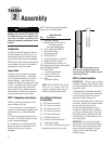
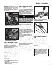
IMPORTANT: Check gear oil level in both
transmissions after the first 2 hours of
new tiller operation, then every 30
operating hours thereafter. See Section 5
for instructions.
STEP 7: Add Motor Oil to Engine
1. Before adding motor oil, park the tiller
on level ground. Level the engine by
placing a sturdy block under the tines or
the tines depth regulator bar.
2. Refer to the Engine Owner’s Manual
provided with your tiller for detailed infor-
mation on how to add motor oil and for
motor oil specifications.
IMPORTANT: Two 20 oz. bottles of motor
oil are included with your tiller. Check the
oil level as instructed in the Engine
Owner’s Manual provided with your tiller
BEFORE pouring the full amount of each
bottle into the engine.
IMPORTANT:
• Change engine oil after first 2 hours of
new operation.
• Check engine oil level every 5 hours of
operation or each use.
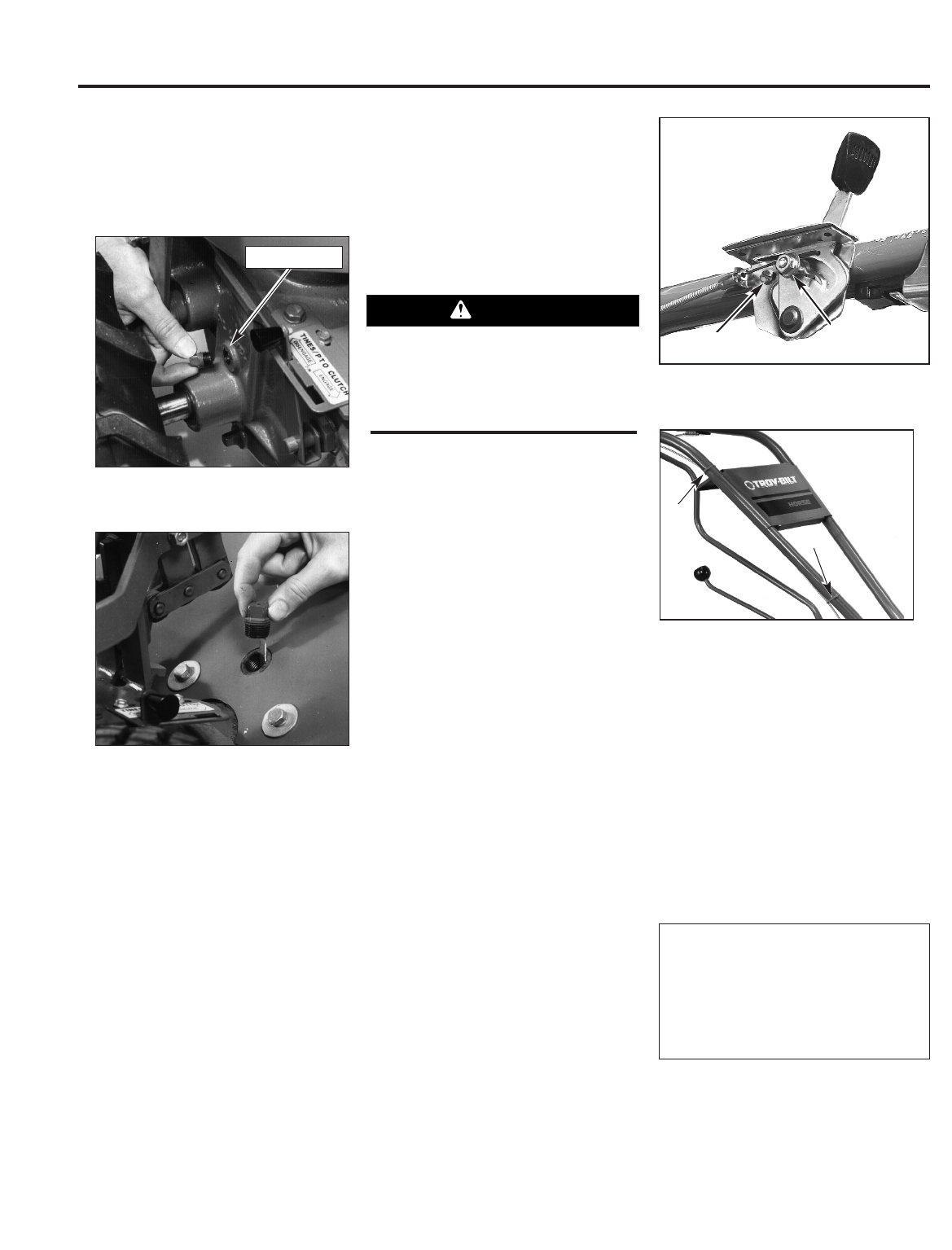
STEP 8: Attach Engine Throttle
Lever and Cable
For shipping purposes, the throttle cable,
together with the throttle lever, is wound
around the engine. Carefully unwind the
cable. If the throttle control label is
covered with a clear protective coating,
peel it off.
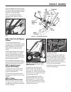
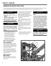
To attach the throttle lever and cable:
1. Run the throttle cable up the inside
edge of the right handlebar and position
the lever as shown in Figure 2-14.
2. From the outside of the handlebar,
insert the curved head screw (A, Figure 2-
14), through the handlebar and the center
hole in the throttle lever mounting
bracket.
3. Loosely install the flanged lock nut
and move the throttle lever back to the
STOP position.
4. From the lever side of the bracket,
thread a pan head screw (B, Figure 2-14)
through the small hole in the throttle lever
bracket and into the handlebar. Tighten
the screw securely.
5. Securely tighten both the flanged lock
nut and the curved head screw.
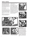
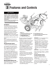
6. Use two plastic ties to secure the
throttle cable to the right handlebar in two
places (Figure 2-15). Loop each tie
around the handlebar and cable (serrated
side faces in) and pull the ties tight. Trim
the ends.
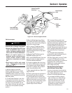
Figure 2-12: Checking oil level on
Power Unit Transmission.
Figure 2-13: Checking oil level on
Tine Attachment Transmission.
To avoid electric shock from a short
circuit (electric start tillers only), never
allow the throttle cable to touch the
battery. Route cable below the battery,
on the outside of the battery holder.
WARNING
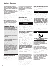
Figure 2-14: Engine Throttle Lever
position and installation.
Figure 2-15: Plastic Ties placement
on handlebars.
Oil Level Hole
B
A
Tie
Tie
Assembly is complete for recoil start
tillers. See Assembling The Electric
Start System if you own an electric
start tiller; otherwise, refer to Section
3,
Controls for information on tiller
controls.
STEP 9: Adjust Air Pressure in
Tires
For shipping purposes, the tires may be
overinflated. Check the air pressure in
each tire and adjust them to between 10
and 20 pounds per square inch. You
must inflate each tire to equal air
pressures to prevent the tiller from pulling
to one side.