


8
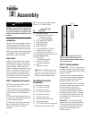
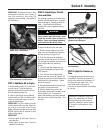
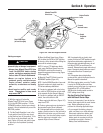
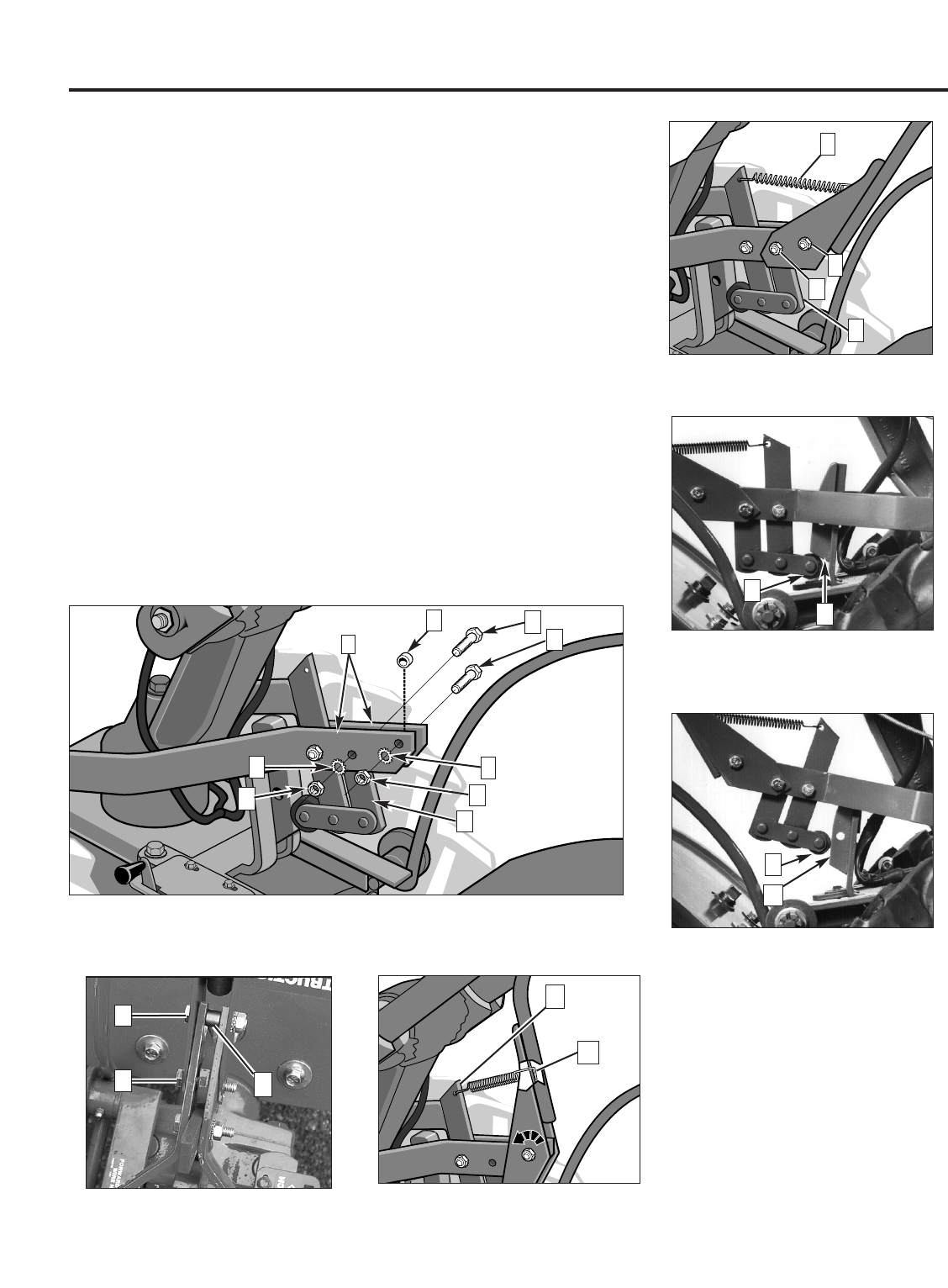
Figure 2-6: Illustration shows the yoke plates (H), nuts, washers, and
screws (A, E, B, F, D, G), bushing (C), and long and short links (I, J).
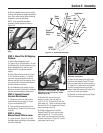
Figure 2-7: Drive Lever assembly.
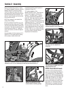
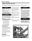
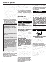
Figure 2-11: Neutral position; roller
(T) rests against middle area of the
adjustment block (U).
A
I
B
C
H
D
E
F
G
Figure 2-10 Forward position; roller
(T) rests under the adjustment
block (U).
U
T
T
U
Figure 2-8: Clutch pawl spring. Tilt
Wheels\Tines\PTO Lever fully
forward before installing spring.
N
M
Section 2: Assembly
Figure 2-9: Fully assembled
Wheels/Tines/PTO Lever assembly.
K
J
L
Q
R
S
STEP 6: Check Gear Oil Levels
Your tiller has two separate transmis-
sions: one for the Power Unit (Figure 2-
12), the other for the Tine Attachment
(Figure 2-13). Both transmissions were
filled at the factory with SAE #85W–140
weight gear oil (with an A.P.I rating of
GL-4). Check level in both transmis-
sions to verify that they are still correct.
See Section 5,
Transmission Gear Oil
Maintenance for complete information
on how to check and fill the transmis-
sions.
P
Remove the temporary screw (J, Figure
2-7) from the forward holes and move the
Wheels/Tines/PTO Lever fully forward.
Install the wider hook end of the clutch
pawl spring (M, Figure 2-8) down into the
small hole at the end of the handle. Use
pliers to insert the other end into the hole
in the long link bar (N).
NOTE: Do not bend or over stretch the
spring while installing.
6. Pull the Wheels/Tines/PTO Lever back
to align the forward most holes (Q, Figure
2-9) in the yoke plate with the holes in the
lever plates. Also align the bushing that is
inside the short link bar (P). Install the
screw, star washer, and nut, then tighten
securely.
Securely tighten all other hardware (Q, R,
Figure 2-9). Also ensure that the spring
(S) is properly seated at both ends.
Completed assembly should appear as
illustrated in Figure 2-9.
7. Test the operation of the
Wheels/Tines/PTO Lever. Push the lever
down until it engages in the Forward
position. The clutch roller (T, Figure 2-
10) must rest beneath the adjustment
block (U). Next, move the lever up to the
Neutral position. The clutch roller (T,
Figure 2-11) should rest on the face of the
adjustment block (U). To test Reverse, lift
and hold the lever all the way up in
Reverse position, then let it go. The lever
should automatically return to the Neutral
position (Figure 2-11). If not, do not use
the tiller. See your local authorized dealer
or call the Factory Technical Service
Department for instructions.