


Section
3
Features and Controls
11
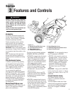
Introduction
This section describes the location and
function of the controls and features on
your tiller. Refer to Section 4,
Operation
for detailed operating instructions.
Practice using these controls, with the
engine shut off, until you completely
understand the operation of the controls
and feel confident with each of them.
IMPORTANT: Refer to the separate engine
manufacturer’s Engine Owner’s Manual
for information about the controls on the
engine.
NOTE: All references to left, right, front
and rear of the machine are based on a
position behind the handlebars and facing
forward.
PTO Attachments Feature
In addition to powerful tilling capability,
you can quickly convert your machine
into a PTO (Power Take-Off) Power Unit
that is capable of towing or powering
various TROY-BILT attachments.
You can access this capability by
removing the tines attachment (powered
by the PTO Power Unit). The PTO Power
Unit is then available for engine powered
attachments, or for pulling or towing non-
powered attachments. See Section 4,
PTO Power Unit for detailed information
on installing and operating TROY-BILT
PTO attachments.
Wheels/Tines/PTO Drive Lever
Use the Wheels/Tines/PTO Drive Lever (A,
Figure 3-1) to engage and disengage
power to the transmission.
This lever has three operating positions:
FORWARD, NEUTRAL and REVERSE.
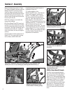
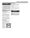
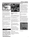
• FORWARD is engaged when the lever is
moved down until the clutch roller (G,
Figure 3-2) engages into the detent
position under the adjustment block (H,
Figure 3-2). You will definitely feel the
lever engage into this position.
Use the FORWARD setting to move the
wheels and tines forward, or to apply
power to an optional PTO (Power Take
Off) attachment. (See also
Forward
Interlock Levers.)
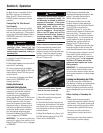
To stop the wheels, tines or any PTO
attachment, move the lever to NEUTRAL
by tapping the lever upwards (Figure
3-3) and releasing.
• REVERSE is engaged when the lever is
pushed (with an open palm) all the way
up and held in that position (Figure 3-4).
Use this setting to move the wheels in
reverse. To stop moving in reverse,
release the lever; it automatically returns
to the NEUTRAL position.
IMPORTANT: Do not operate the tines or
any PTO attachment in REVERSE.
• NEUTRAL is this control’s normal non-
operating position. The lever returns to
NEUTRAL when it is tapped out of the
FORWARD position or released from the
REVERSE position. NEUTRAL position
is between FORWARD and REVERSE
(Figure 3-3). Use this setting to stop
the wheels, tines or any PTO attach-
ment.
IMPORTANT: Always shift to NEUTRAL
before starting the engine or before
engaging the wheels, tines or any PTO
attachment.
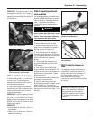
Forward Interlock Levers
The Forward Interlock Levers (B,
Figure 3-1) are attached under each
handlebar grip.
You must squeeze at least one of these
interlock levers up against the handlebar
grip whenever the Wheels/Tines/PTO
Drive Lever is engaged in FORWARD
position.
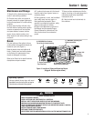
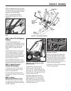
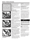
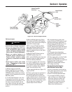
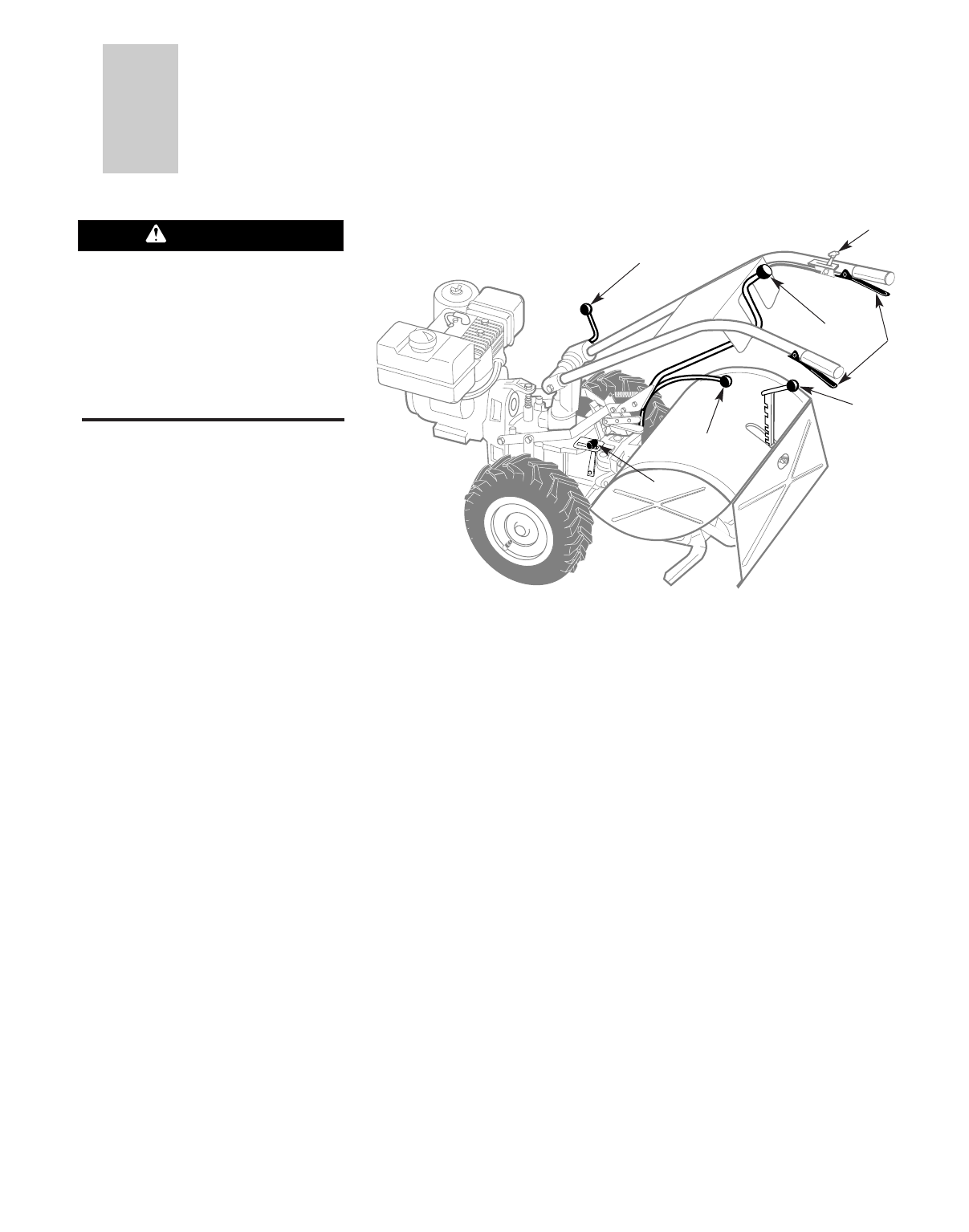
Figure 3-1:
A– Wheels/Tines/PTO Drive Lever E– Depth Regulator Lever
B– Forward Interlock Levers F– Handlebar Height Adjustment Lever
C– Wheel Speed Lever G– Engine Throttle Lever
D– Tines/PTO Clutch Lever
A
G
B
C
D
E
F
Before operating your machine,
carefully read and understand all
safety, controls, operating instructions
in this Manual, the separate Engine
Owner’s Manual and on the decals on
the machine.
Failure to follow these instructions can
result in serious personal injury.
WARNING