


Your tiller is a self-contained PTO (Power
Take-Off) Power Unit that was shipped
with a tine attachment installed. The tine
attachment can be quickly removed and
replaced with other optional attachments.
The following instructions will familiarize
you with your PTO Power Unit. Please
read these pages carefully.
The following steps explain how to
remove and replace the tine attachment.
You will need a 3/4" wrench (minimum
12" long for leverage).
Removing Tine Attachment
1. Move the tiller to level ground.
2. Be sure the engine is stopped, the
electric start key is removed, and the spark
plug wire is disconnected and moved away
from spark plug.
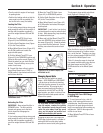
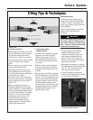
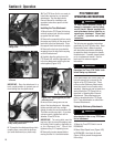
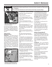
3. Place a sturdy support under the
engine to prevent the engine from tipping
forward when the tine attachment is
removed (Figure 4-23).
4. Place the Wheels/Tines/PTO Drive Lever
into NEUTRAL (Figure 4-22).
5. Place Tines/PTO Clutch Lever in
DISENGAGE (Figure 4-22).
6. Place Wheel Speed Lever into FREE
WHEEL (Figure 4-22).
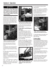
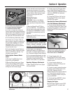
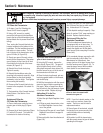
7. Loosen the two swing-out bolts (Figure
4-24) that connect the power unit trans-
mission to the tine attachment and swing
out the bolts (Figure 4-25).
HINT: Loosening swing-out bolts can be
difficult. Use an extra-long wrench for
leverage.
8. Tip the PTO power unit forward about
one inch with one hand while pulling the
tine attachment back (Figure 4-26). The
guide pin on the power unit will slide out
of the guide hole in the tine attachment
(Figure 4-27).
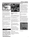
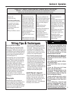
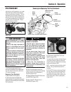
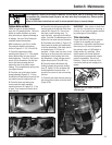
Removing And Replacing The Tine Attachment
PTO POWER UNIT
Figure 4-21: PTO Power Unit and tine
attachment.
Before operating your PTO Power
Unit for the first time, make sure that
you have:
• Read all the safety instructions in
Section 1 of this Manual and in the
Manual supplied with any attach-
ment.
• Read the controls information and
operating procedures for the tiller
and engine described in Sections 3
and 4 of this Manual and in the
Engine Owner’s Manual.
• Read and understand the assembly
instructions, controls information,
and operating procedures for the
attachment as described in the
Attachment Owner’s Manual supplied
with the attachment.
Section 4: Operation
TO AVOID PERSONAL INJURY OR
DAMAGE TO EQUIPMENT:
• Stop the engine, remove the electric
start key, disconnect the spark plug
wire and let the engine and muffler
cool before removing or installing any
attachment.
• Do not place hands, tools, or any
object near or inside the PTO access
area while the engine is running.
• When removing or replacing the tine
attachment, be careful of the sharp
edges on the tiller hood. Wear thick
gloves for hand protection.
• When the tine attachment is
removed, always prop it up with a
block to prevent the attachment from
falling forward.
CAUTION
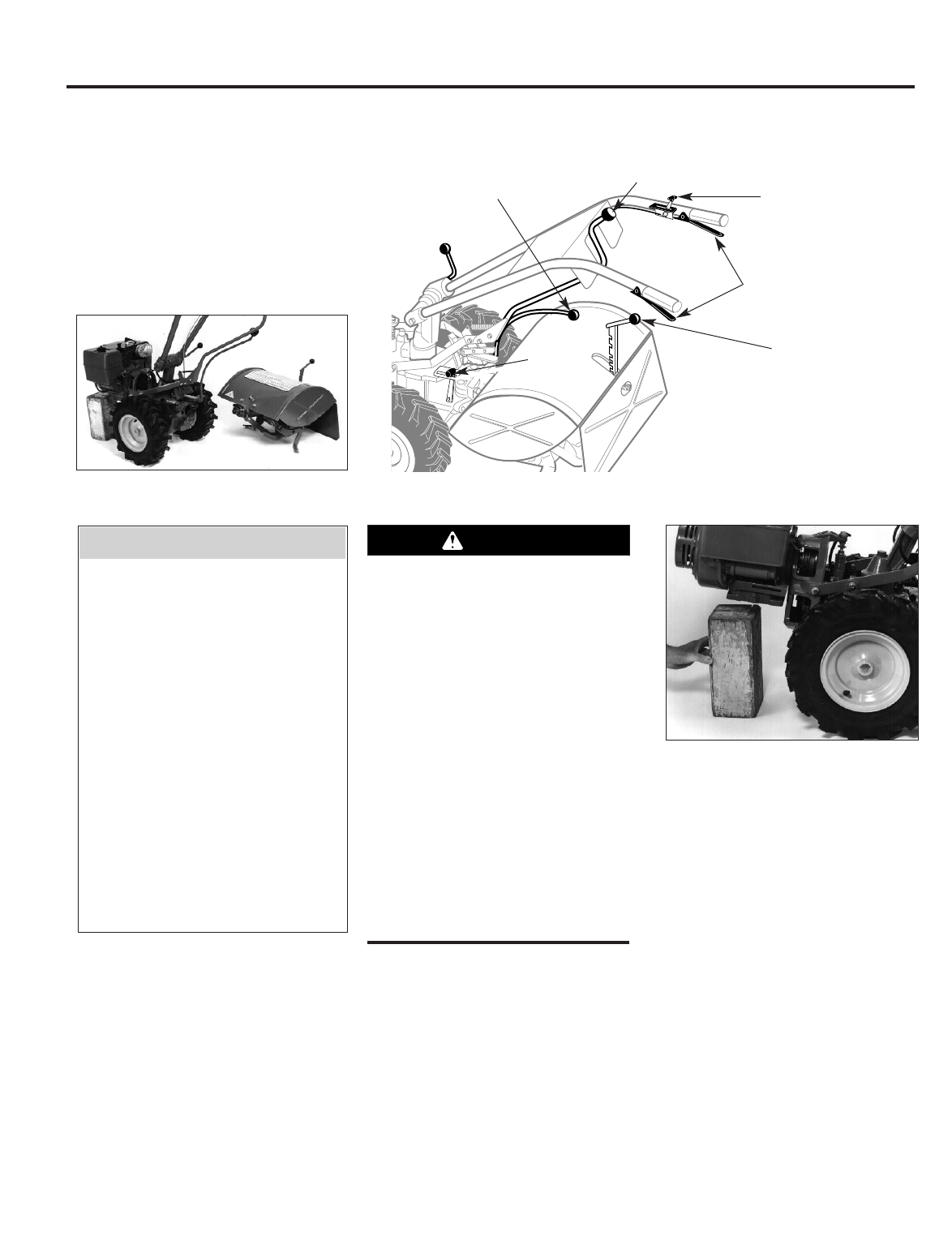
Figure 4-23: Block up engine.
VERY IMPORTANT
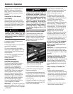
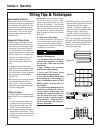
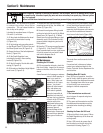
Figure 4-22: PTO Power Unit controls.
Wheels/Tines/PTO
Drive Lever
Forward
Interlock Levers
Depth
Regulator
Lever
Wheel
Speed
Lever
Engine
Throttle Lever
Tines/PTO
Clutch
Lever
25