


I]
Assembly
WARNING
To prevent personal injury or
property damage, do not start
the engine until all assembly
steps are complete and you
have read and understandthe
safety and operating instruc-
tions in this manual.
Introduction
Carefullyfollow theseassembly steps to
correctly prepareyour tiller for use. It is
recommendedthat you readthis Section
in its entirety beforebeginning assembly.
NOTE: Enginesylesvary by model. The
engineon your tiller may appeardiffer-
ently than those shown in illustrations
and Figuresthroughout this manual.
Inspect unit
Inspect the unit and carton for damage
immediately after delivery. Contactthe
carrier (trucking company) if you find or
suspect damage. Inform them of the
damageand request instructions for filing
aclaim. To protect your rights, put your
claim in writing andmail a copy to the
carrierwithin 15 daysafter the unit has
beendelivered.
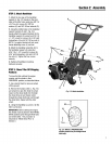
STEP1: UnpackingInstructions
1. Removeany cardboardinserts and
packagingmaterial from the carton.
Removeany staplesfrom the bottom of
thecarton and then lift the carton up and
off the unit.
2.Thetiller is heavyandyou should not
attempt to remove itfrom the shipping
platform until the handlebarsare
installed. Theprocedurefor removing the
tiller is explained in Step3 of these
assembly steps.
NOTE:Becareful notto severelybendany
of the control cables on the unit.
3. Removeall unassembledparts and
the separatehardwarebag from the
carton. Checkthat you havethe items
listed below (contact your localdealer or
the factory if any items are missing or
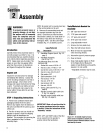
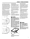
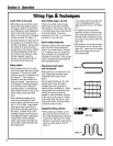
damaged). NOTE: Usethe screw length
template (Fig. 2-1) to identify screws.
LoosePartsList
Qty. Description
1 HandlebarSupport (seeA, Fig. 2-2,
page7)
1 HandlebarAssembly
(seeK, Fig.2-2)
Thefollowing itemsarein the
hardwarebag:
1 Slotted hd. screw, #10-24 x 2"
1 Hexhd. screw, 1/4-20x 1-1/4"
6 Curvedhd. screw, 5/16-18 x 1-1/2"
2 Hexhd. screw, 3/8-16 x 3/4"
2 Flatwasher,3/8"
6 Split Iockwasher,5/16"
1 Hexlocknut, 1/4"-20
6 Hexnut, 5/16"-18
2 Hexlocknut, 3/8"-16
1 Hexnut,#10-24
1 Spring, cable(seeW, Fig. 2-5,
page8)
1 Bracket,forward clutch cable (see
P,Fig. 2-5, page8)
1 Bracket,reverseclutch cable(see
BB,Fig. 2-8, page9).
IMPORTANT:Motoroil mustbeaddedto
the enginecrankcasebeforethe engine
isstarted. Followthe instructionsinthis
"Assembly" section.
NOTE:LEFTand RIGHTsides of the tiller
are asviewed from the operator's
position behindthe handlebars.
Tools]MaterialsNeededfor
Assembly
(1) 3/8" open-endwrench*
(2) 7/16" open-endwrench*
(1) ll2" open-endwrench*
(2) 9/16" open-endwrench*
(1) Largeadjustable wrench
(1) Scissors (to trim plasticties)
(1) Ruler (for belttension check)
(1) Block of wood (to support tiller
when removing wheels)
(1) Automotive-type air pressure gauge
(1) Cleanoilfunnel
(1) Clean,high-quality engineoil. Refer
to the EngineOwnerManualfor
engineoil specifications and quantify
required. Do not overfill.
* Adjustablewrenches may beused.
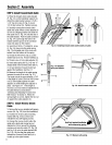
Figure2-1: Toidentifylengthofscrew,
placescrewontemplateasshownand
measuredistancebetweenbottomofscrew
headandtipofscrew.
6