


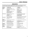

Section5: Maintenance
WARNINGBeforeinspecting,cleaning or servicingthe unit, shut off engine, wait for all I"
partsto cometo a completestop, disconnectspark plugwire and movewire away from spark ....t....[
plug. Failure to follow these instructions can result in serious personal injury or
propertydamage.
B. To Drain theTransmissionGearOil:
DANGER
Gasoline is highly flammable
and its vaporsexplosive. Fol-
low these safety practices to
prevent injury or property
damage from fire orexplosion.
• Allow the engine and
muffler to cool before
draining the tiller's gasoline
tank.
• Do not allow open flames,
sparks, matches or smoking
in the area.
• Wipe away spills and push
tiller away from spilled fuel.
• Use only an approved fuel
container and store it safely
out ofthe reach of children.
• Do not store gasoline where
its vapors could reach an
open flame or spark, or
where ignition sources are
present (such as hot water
and space heaters, furnaces,
clothes dryers, stoves,
electric motors, etc.)
Thetransmission gear oil does not need
to bechanged unless it hasbeencontam-
inatedwith dirt, sand or metal particles.
1. Drain gasolinefrom the fuel tank or
run the engine until thefuel tank is empty.
See"DANGER"statement above.
2. Drainthe oil from the engine.
3. Removethefour screws (B, Figure5-2)
and washersfrom thetransmission cover
and removethe cover and gasket.
4. Removethe left-sidewheel.
5. Tilt the left-sidewheel shaft into a
drain panand allow thegear oil to drain
through the top of the transmission.
6. Nter draining oil, reinstall the wheel,
install a newgasket (do not reuseold
gasket)and screwon transmission cover.
7. Refill transmission using GL-4 gearoil
(SAE85W-140 or SAE140).
8. Refill the enginewith motor oil and
replenishthe fuel tank with gasoline.
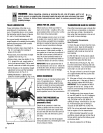
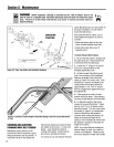
Figure5-2: Removeoilfillplug(A)tocheck
gearoillevelandtoaddgearoil, Remove
fourcoverscrews(B)todraingearoil.
TINES
Thetines wear with useand they should
beinspectedat the beginning of each
tilling seasonandafter every30 operating
hours. Thetines canbe replacedindivid-
uallyor as a complete set. Referto the
Parts List Section of this manualfor tine
identification information.
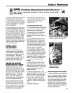
WARNING
This is a CRT(counter-rotating
tine) tiller and its tines must
be mounted in the direction
shown in Figure 5-3. If
mounted with curves in the
opposite direction, tiller will
dig poorly and be more likely
to runbackward.
Failure to comply could result
in personal injury or property
damage.
NOTE:You must first remove thetiller
hood before removing eithera single tine
holder or individualtines. Removethe
two screws at thefront of the hood and
the two screws atthe rear ofthe hood
and lift off the hood. Besureto replace
the hood securely after changinga tine or
tine holders.
A. Tine Inspection:
With use, thetines will becomeshorter,
narrowerand pointed. Badlyworn tines
will result in a loss of tilling depth and
reducedeffectivenessin general,and
specifically whenchopping up and
turning under organic matter.
B. Removingand Installing
Tine Assemblies
1. Usea 9/16" socket,6" extension, a
ratchet,and a 9/16" boxend wrench to
loosenthe nut (A, Figure5-3) and screw
(B) that secure thetine holder to the tine
shaft.
2. Usea rubber mallet to tap thetine
holder loose. Slidetine assembly off.
3. RepeatSteps1 and 2 aboveto remove
the other tine assembly.
4. Installing the tine assembly is simply
the reverseof its removal. First besure
to removeany rust, unevenspots or burrs
from the tine shaft usingfine sandpaper.
Thengreasethe tine shaft beforerein-
stalling the tine assemblies. Be sureall
the cutting edgesface so they will enter
the soil first when thetiller is moving
forward- this means the cutting edge on
the top of eachtine faces towardthe
operator position. Tighten hardware.
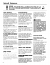
C. Removingand Installing
Individual Tines
1. Usetwo 9/16" box endwrenches to
removethetwo screws(C, Figure5-3)
and nuts (D) that securethe tine to its
tine holder.
NOTE:If the nuts are rusted,apply pene-
trating oil, then loosenthe hardware.
2. When installing individual tines, do so
in the reverseorder from which they were
removed. Thetwo sets of inboardtines
are installed so one set facestoward the
transmission and the otherfacesaway
from it. Thesingle outboardtine set
facestoward the transmission housing.
Also besure the cutting edge at the top
of eachfine faces toward the operator
position. (SeeFigure5-3.)
21