


Section2: Assembly
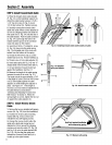
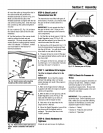
4. Insertthe cableup through the slot in
the cablebracketand position the
threadedassembly asshown in Fig. 2-8.
Makesurethat theflat sideof the
threadedassembly is aligned with the flat
sideof the mounting hole. Slidethe large
hexnut (DD) up the cableand tighten it
securely.
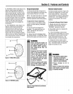
5. Usea cabletie (EE,Fig. 2-9) to fasten
the reverseclutch cableto the left side
handlebar.
6. Testthe function of the reverseclutch
cable by pulling the knob out and
releasingit. Theknob should return to its
neutralposition (resting against bracket)
when it is released. If it doesn't, contact
your localdealer or the factory for
technical assistance.
AA_
I
DD
FlatSide
Fig.2-8:Installreversecablemounting
bracketandthereverseclutchcable.
STEP6: CheckLevelof
TransmissionGearOil
Thetransmission was filled with gear oil
atthe factory. However,you should check
the gear oil levelto make certain it is
correct.
IMPORTANT:Do not operatethe tiller if
the gear oil levelis low. Doingso will
result in severedamageto the transmis-
sion components.
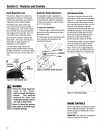
1. Putthe tiller on levelground. Pull the
Depth RegulatorLever (FF,Fig. 2-10)
backand then adjust it up or down to the
notch that makesthe tiller level.
2. Removethe oil fill plug (GG,Fig.2-11)
from the transmission housing and look
into theoil fill hole. You will seethe main
drive shaft on one sideof the hole.
8. The gearoil level is correct if the gear
oil isapproximately halfwayup the side of
the drive shaft.
4. If the gear oil level is low, add gear oil
by referringto "A. To Checkthe Transmis-
sion GearOil Level" in Section 5.
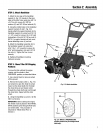
STEP 7: Add Motor Oil to Engine
The tiller isshippedwithoutoil in the
engine.
IMPORTANT:Do not start the engine
without first adding motor oil. Severe
engine damagewill result if the engine is
run without oil.
1. Referto the EngineOwner's Manual
(suppliedwith tiller) for engine oil specifi-
cations and capacities.
2. With the tiller on levelground, pull the
Depth RegulatorLever (FF,Fig. 2-10)
backand then slide it up or downas
necessaryuntil the engine is level.
3. Add motor oil asdescribed in the
EngineOwner's Manual.
4. Move the Depth Regulator Leverall the
way down until the highest notch is
engaged. This placesthe tines in the
"travel" position.
Fig, 2-10: AdjustDepthRegulator Lever.
Fig.2-11:Removegearoilfillplug.
STEP9: CheckAir Pressurein
Tires)
Usea tire pressuregauge to checkthe air
pressure in bothtires. Deflateor inflate
both tires equallyto 15-to-20 PSi
(pounds persquare inch). Be surethat
both tires are inflated equallyor the unit
will pull to one side.
IMPORTANT: This completes the
assembly steps. Before operatingyour
tiller, make sureyou readthe following
Sections in this Manual, aswell as the
separateEngineOwner's Manual:
• Section 1: "Safety"
• Section 3: "Featuresand Controls"
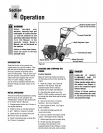
• Section 4: "Operation"
Fig. 2-9." Routereverseclutchcable(CC)as
shown. Attachtohandlebarwith cabletie
(EE).
STEP 8: Check Hardware for
Tightness
Checkall nutsandscrewsfortightness.