


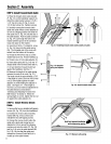
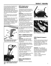

STEP 2: Attach Handlebar
1. Attachthe two legsofthe handlebar
support (A, Fig.2-2) loosely to the inner
sides of the tiller frame using two 3/8"-16
x 3/4" hexhd. screws (B), 3/8" flat
washers(C) and 3/8"-16 hex Iocknuts(D).
2. Using the middle holes in the handlebar
support brackets (Eand F,Fig.2-2),
loosely attachthe support brackets to the
handlebarsupport (A)using two 5/16"-18
x 1-1/2" curved hd. screws (G),5/16" split
Iockwashers (H)and 5/16"-18 hexnuts (I).
NOTE:If a support bracketwill not move,
loosenattaching screw (J) and nut.
3. Attach the handlebarassembly (K) to
the handlebarsupport (A) usingfour
5/16"-18 x 1-1/2" curved hd. screws (G),
5/16" split Iockwashers(H) and 5/16"-18
hex nuts (I). Tighten the four screws
securely.
4. Tighten all handlebar mounting
hardwaresecurely.
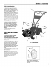
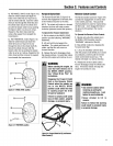
STEP3: MoveTiller OffShipping
Platform
To movethe tiller without theengine
running, putthe wheels in their
FREEWHEELposition, asdescribed below.
1. Usea sturdy block to raiseonewheel
off theground.
2. Removethe hairpin cotter (L, Fig.2-3)
and wheeldrive pin (M). Slide the wheel
inward on the wheelshaft (N). Reinstall
thewheel drive pin and hairpin cotter
through the wheelshaft only (not through
thewheel hub). Repeatwith the other
wheel.
3. Using the handlebaras a lever, roll the
tiller to aflat area.
IMPORTANT:Beforestarting the engine,
thewheels must be placedin their WHEEL
DRIVEposition (pins through wheel hubs
and wheelshaft). This procedureis
described in "Wheel Drive Pins" in
Section 3.
\
B
C
D
Fig. 2-2: Attachhandlebar.
I
L
Fig. 2-3: Wheel in FREEWHEELING
position(wheel drivepin throughwheel
shaRonly).
Section2: Assembly