


8 Section 3 — ASSembly & Set-Up
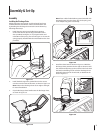
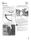
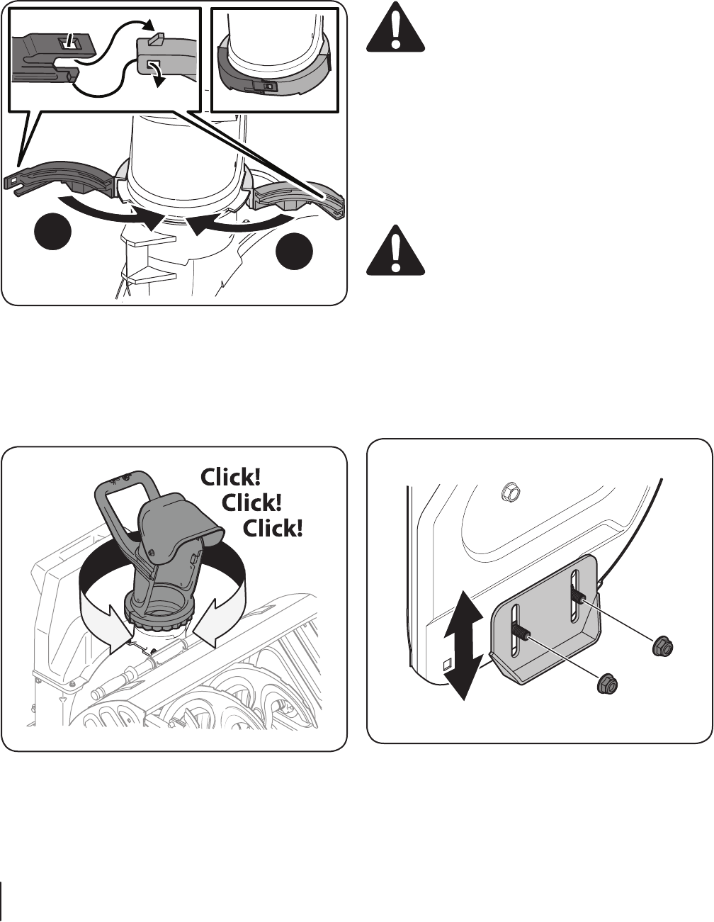
5. Secure the chute band to itself by first aligning the two
snap-fit features and pushing the two ends (1 & 2) together
as shown. Be sure both tabs on the two ends engage each
other, as shown in the top left inset of Figure 3-5. When
properly assembled, the chute band will appear as in the
top right inset of Figure 3-5.
1
2
Figure 3-5
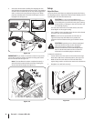
IMPORTANT: If you need to remove the chute for any reason,
a screw driver must be used to release the locking tabs shown
above in the left inset of Figure 3-5.
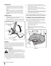
Note: If the installation has been completed properly, a
click! click! click! sound will be heard when rotating the
chute to the left and right. See Figure 3-6.
Figure 3-6
Set-up
Adjust Skid Shoes
The snow thrower skid shoes are adjusted upward at the factory
for shipping purposes. Adjust them downward, if desired, prior to
operating the snow thrower attachment.
CAUTION : It is not recommended that you
operate this snow thrower attachment on gravel as
it can easily pick up and throw loose gravel, causing
personal injury or damage to the snow thrower and
surrounding property.
• For close snow removal on a smooth surface, raise skid
shoes higher on the auger housing.
• Use a middle or lower position when the area to be cleared
is uneven, such as a gravel driveway
NOTE: If you choose to operate the snow thrower on
a gravel surface, keep the skid shoes in position for
maximum clearance between the ground and the shave
plate.
CAUTION: Operating a snow thrower equipped
with steel skid shoes may result in damage to
natural stone paver surfaces (e.g. sandstone,
bluestone, limestone). Refer to the Replacement
Parts or Attachments & Accessories sections for
information on available polymer skid shoes.
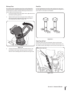
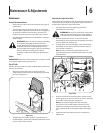
To adjust the skid shoes:
1. Loosen the four hex nuts (two on each side) and carriage
bolts. Move skid shoes to desired position. See Figure 3-7.
2. Make certain the entire bottom surface of skid shoe is
against the ground to avoid uneven wear on the skid shoes.
3. Retighten nuts and bolts securely.
Figure 3-7