


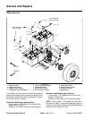
Workman e2050/e2065
Page 3 – 24
Electrical System (Rev. B)
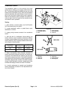
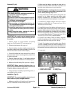
Accelerator Switch
The accelerator switch is a four terminal, two circuit
switch that is located on the control pedal frame (Fig.
38). The Workman e2050 and e2065 use only one of the
switch circuits (terminals 3 and 4). When the accelerator
pedal is depressed, the switch allows a closed circuit (in-
put) for the controller to allow traction motor operation.
When the accelerator pedal is released, the switch pro-
vides an open circuit (no input) for the controller to pre-
vent traction motor operation.
Testing
1. Park vehicle on a level surface, turn On/Off switch
OFF and remove key from switch.
2. Locate accelerator switch on pedal frame under
dashboard of vehicle.
3. Unplug wiring harness connector from accelerator
switch.
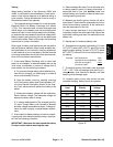
4. With the use of a multimeter (ohms setting), the
switch functions may be tested to determine whether
continuity exists between the switch terminals for both
switch positions. Verify continuity between switch termi-
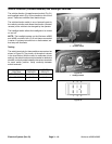
nals using the following table:
PLUNGER
POSITION
CONTINUITY
NO
CONTINUITY
IN 1 and 2 3 and 4
OUT 3 and 4 1 and 2
5. When reconnecting wiring harness connector to
switch after testing, harness connector and switch ter-
minal area should be filled with dielectric gel (see Spe-
cial Tools) to prevent corrosion of connection terminals.
Apply gel fully to both harness connector and switch ter-
minal area, plug harness connector into switch to distrib-
ute gel, unplug harness connector, reapply gel to both
surfaces and replug harness connector into switch.
6. If switch replacement is needed, see Accelerator
Switch Adjustment procedure in the Adjustments sec-
tion of this chapter.
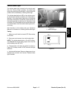
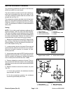
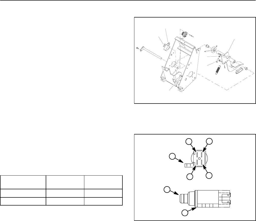
1. Accelerator pedal
2. Accelerator switch
3. Plate
4. Screw (2 used)
5. Stop cap screw
6. Lock nut
Figure 38
1
2
3
4
5
6
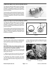
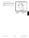
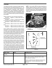
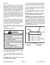
1. Terminal 1
2. Terminal 2
3. Terminal 3
4. Terminal 4
5. Switch plunger
6. Mounting tab
Figure 39
END VIEW
SIDE VIEW
3
5
6
1
6
2
4