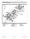
Workman e2050/e2065Page 5 – 14Chassis (Rev. B)
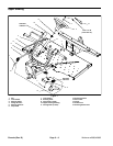
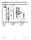
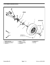
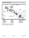
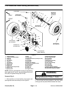
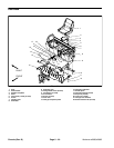
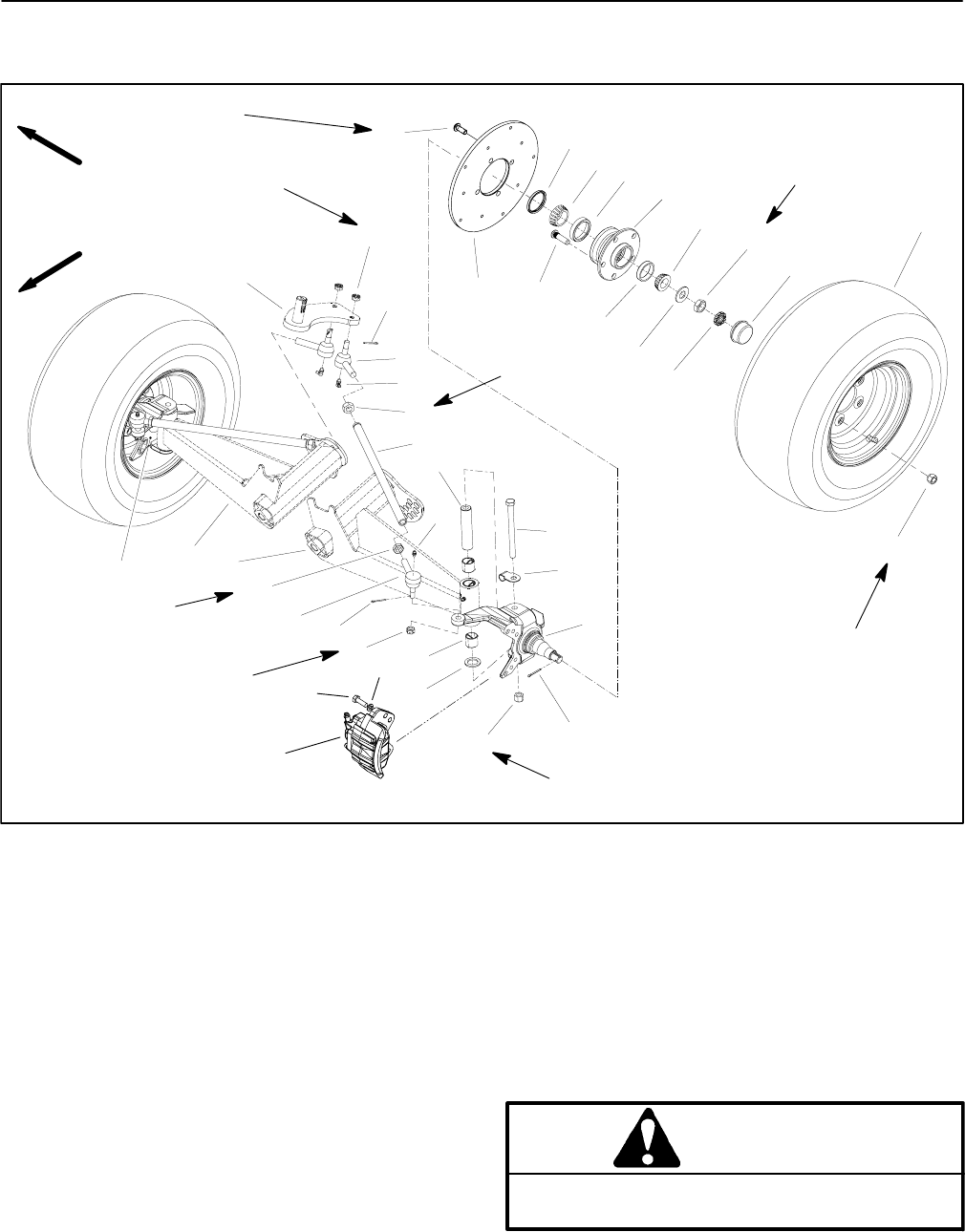
Front Wheels and Lower Steering (Workman e2065)
1. Wheel assembly
2. Lug nut (5 used per wheel)
3. Dust cap
4. Cotter pin
5. Nut retainer
6. Jam nut
7. Tab washer
8. Bearing cone
9. Bearing cup
10. Wheel hub
11. Wheel stud (5 used per hub)
12. Bearing cup
13. Bearing cone
14. Seal
15. Brake rotor
16. Socket head screw (4 used per rotor)
17. Lock nut
18. LH spindle
19. Cap screw
20. Brake hose bracket
21. Bushing (2 used per A–arm)
22. Thrust washer
23. RH spindle
24. Castle nut
25. Cotter pin
26. Kingpin sleeve
27. Ball joint (RH thread)
28. Jam nut (RH thread)
29. Tie rod tube
30. Pitman arm
31. Ball joint (LH thread)
32. Grease fitting
33. Jam nut (LH thread)
34. A–arm (RH)
35. A–arm (LH)
36. Grease fitting
37. Brake caliper (LH shown)
38. Lock washer (2 used per caliper)
39. Cap screw (2 used per caliper)
Figure 6
20 to 25 ft–lb
(27 to 34 N–m)
75 to 100 ft–lb
(102 to 136 N–m)
20 to 25 ft–lb
(27 to 34 N–m)
45 to 65 ft–lb
(61 to 88 N–m)
FRONT
RIGHT
Loctite #242
18
22
23
24
21
30
27
26
29
28
33
34
19
20
31
16
24
35
36
25
37
38
39
4
15
17
32
25
13
14
10
8
7
5
1
3
2
6
9
12
11
45 to 55 ft–lb
(61 to 74 N–m)
45 to 55 ft–lb
(61 to 74 N–m)
See text for
tightening
procedure
NOTE: Both tie rod assemblies consist of the following
parts: ball joints (27 and 31), jam nuts (28 and 33), tie rod
tube (29) and grease fittings (32 and 36).
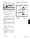
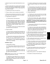
Removal (Fig. 6)
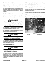
1. Park machine on a level surface, stop engine, set
parking brake and remove key from the ignition.
WARNING
Before jacking up the machine, review and follow
Jacking Instructions in Chapter 1 – Safety.
2. Chock wheels not being jacked up. Jack front wheel
off the ground and place blocks beneath the frame.


