Appendix D: Performance Verification
73A-270 Arbitrary Pulse/Pattern Generator Module
75
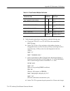
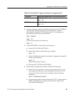
b. Set the 73A-270 to generate a 500 Hz square wave and then stop the
pulse pattern:
set VX270
IBWRT "0S3R0A0M101L104L0C0B
"
(Verify a square wave)
IBWRT "Q"
(Verify no pattern)
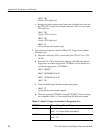
c. Using the oscilloscope probe, check that S1 pin 2 (Transmission In
Progress A, active high), is a TTL low level and that pin 3 (Transmission
In Progress A, active low) is a TTL high level.
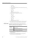
d. Restart the 500 Hz pulse pattern with the command below and check that
pin 2 of S1 is now a TTL high level and pin 3 is a TTL low level.
IBWRT "0B"
(Check that pin 2 is high and pin 3 is low)
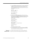
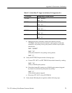
e. Move the coaxial cable to TTL OUT B. Program the 73A-270 to
generate the 500 Hz pulse-pattern on TTL OUT B and then stop the
pulse pattern:
IBWRT "1S3R0A0M101L104L0C0B"
(Verify a square wave)
f. Stop the pattern and again using the oscilloscope probe, check that
Transmission In Progress B (active high), pin 12 of S1 (2nd down from
top right,) is a TTL low level and that Transmission In Progress B
(active low), pin 11 (3rd down from top right,) is a TTL high level.
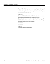
IBWRT "Q"
(Verify no pattern and pin 12 is high and pin 11 is low)
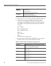
g. Restart the 500 Hz pulse pattern and check that pin 12 of S1 is now a
TTL high level and that pin 11 is a TTL low level.
IBWRT "1C0B"
(Verify pin 12 is high and pin 11 is low)
This completes the 73A-270 verification procedure.


