


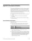

Appendix D: Performance Verification
62
73A-270 Arbitrary Pulse/Pattern Generator Module
This sequence verifies that the 73A-270 configures correctly and communicates
properly with your system controller.
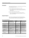
Equipment
Requirements
Oscilloscope (item 1)
50 W Coaxial Cable (item 5)
Prerequisites All prerequisites listed on page 56
1. Send the appropriate commands to the Slot 0 device to get the primary/sec-
ondary GPIB address of the 73A-270, 73A-541, and VX4790A. Place these
addresses into the IBCONF configurator for the VX270. VX541, amd
VX4790A GPIB device.
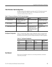
2. Verify that the 73A-270 responds to setup commands with the following
steps:
a. Connect the 73A-270 TTL OUT A to Ch-1 of the oscilloscope (2 V/div,
250 ns/div, 1 MW input impedance).
b. With the following commands, set the 73A-270 to the beginning of the
address space, for the first List entry to have a duration of 500 ns
(5×100 ns power-on default resolution) active high, for the second List
entry to have an active low duration of 500 ns and to be designated as
the Last Address, to transmit the list continuously, and finally to begin
transmission of the last selected channel (in this case Ch A, the power-on
default). Verify a 1 MHz 50% duty cycle pulse-pattern.
IBOC (Start GPIB Talker/Listen/Controller program)
IBFIND VX270
IBRD 100
(Observe 00 response)
IBWRT "0A51L54L0C0B"
(Observe 1 MHz square wave)
IBWRT "Q"
(Observe waveform stops)
3. To verify interrupt capability, set the 73A-270, to enable the transmit
complete interrupt (XMIT), and to generate a burst of (63) pulses. Then read
and verify a response of 02. This response means that there is no transmis-
sion in progress, that an interrupt has been generated due to transmission
completion or breakpoint, that the memory is not busy, and that a Memory
Busy Overwrite interrupt has not been generated. Following the read, the
Slot 0 controller will be un-addressed and will acknowledge the interrupt as
an SRQ pending.
VXIbus Interface