


Appendix D: Performance Verification
70
73A-270 Arbitrary Pulse/Pattern Generator Module
IBWRT "0B"
(Verify a TTL high level)
c. Retrigger the pulse-pattern several times and check after each start that
the TTL OUT A signal level alternates between a TTL low level and a
TTL high level.
IBWRT "0B"
(Verify a TTL low level)
IBWRT "0B"
(Verify a TTL high level)
IBWRT "Q"
(Verify that the pulse-pattern stops)
7. Verify channel B operation with the VXIbus TTL Trigger Lines with the
following steps:
a. Move the oscilloscope CH-2 coaxial cable from TTL OUT A to TTL
OUT B.
b. Reset the 73A-270 for channel B to generate a 500 kHz pulse-pattern
triggered by an external trigger from TTLTRG0* and for channel A to
provide the trigger pulse on TTLTRG0*.
IBWRT "80X08T"
IBWRT "0S3R0A0M51L54L1C"
IBWRT "1S1R0A1M11L14L0C"
IBWRT "1B"
c. Verify a 500 kHz signal and then stop the pulse-patter:
IBWRT "Q"
(Verify that the pulse-pattern stopped)
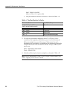
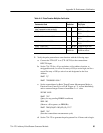
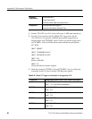
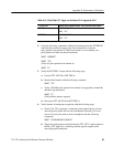
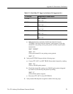
d. Check the remaining TTLTRG1* through TTLTRG7* lines by sending
the commands in table A–7 and verifying the 500 kHz pulse-pattern.
Table A–7:
VXIbus TTL Trigger Line Verification Ch. B triggered by Ch. A
TTLTRG Line Change Setup, & Restart Pattern
TTLTRG1* IBWRT "81X18T"
IBWRT "1B” (Verify a 500 kHz pulse–pattern.)
TTLTRG2* IBWRT "Q82X28T"
IBWRT "1B”