


Appendix D: Performance Verification
73A-270 Arbitrary Pulse/Pattern Generator Module
67
3. To verify the BPLR pulse-pattern phase and ±2 V accuracy, set the 73A-270
to generate a continuous pulse-pattern square wave from both the TTL and
the BPLR outputs with a 10 ms period and a bipolar amplitude of ±2.0V.
Check that the BPLR OUT signal is in phase with the TTL OUT signal and
that the amplitude is ±2.0 V ±2 mV.
SET VX270
IBWRT "0S" or IBWRT "1S"
(Select Ch-A or Ch-B)
IBWRT "1R0A0C51L54L0B"
IBWRT "20P-20N"
(Verify ±2.0 V ±260 mV)
4. Reset 73A-270 for a BPLR OUT amplitudes of ±5.0 V and ±8.7 V and
verify that the corresponding BPLR OUT signals are in phase with the TTL
OUT signal and that the amplitude is within ±260 mV of the value set. Then
change the polarity of the BPLR OUT signal and verify. Finally set the
BPLR OUT signal to 0 V and verify.
IBWRT "50P-50N"
(Verify ±5.0 V ±260 mV)
IBWRT "87P-87N"
(Verify ±8.7 V ±260 mV)
IBWRT "-87P87N"
(Verify ±8.7 V ±260 mV and opposite polarity)
IBWRT "00P00N"
(Verify 0.0 V ± 260 mV)
IBWRT "Q"
(Verify that the pulse-pattern is stopped.)
5. The verification steps in this section should be performed for both BPLR
OUT A and BPLR OUT B channels. If you have not tested both channels,
repeat the steps in this section for the other channel.
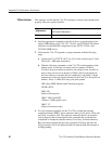
This sequence verifies the operation of the 73A-270 with the VXIbus TTL
trigger lines (8), internal and external triggering and breakpoint recognition.
Triggering, and
Breakpoint Function