


Appendix D: Performance Verification
73A-270 Arbitrary Pulse/Pattern Generator Module
63
NOTE. Make sure the 73A-270 and the Slot 0 Resource Manager are set to the
same INT LEVEL. Also, If an embedded controller is being used, follow the
operating manual for displaying the state of the interrupt lines.
IBWRT "1I63C0B"
IBRD 100
(Observe 02 response)
4. Check for VXIbus Request True event by performing a serial poll and verify
that the response byte is
0x40 (decimal:64)
(i.e. DIO7 = 1)
IBRSP
(Observe 40 response)
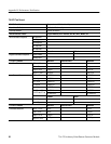
This sequence verifies the time base resolution, the pulse duration multiplier, and
the burst mode for the TTL OUT A and B signals. Complete all steps in this
section for TTL OUT A and then repeat all steps for TTL OUT B.
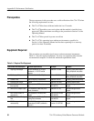
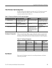
Equipment
Requirements
Oscilloscope (item 1)
Counter/Timer (item 3)
50 W BNC Coaxial Cable (item 5)
Prerequisites All prerequisites listed on page 56
All previous Performance Verification Tests
1. Connect the TTL OUT A (or TTL OUT B) output to Ch-1 of the oscillo-
scope (2 V/div, 1 ms/div, 1 MW input impedance).
2. Verify the time base resolution with the following steps:
a. Select the channel to be tested:
IBWRT "0S" or IBWRT "1S"
(Select TTL OUT A or TTL OUT B)
b. Set the 73A-270 for a 100 ns resolution and then to the beginning of the
address space, for the first List entry to have a of 100 ns active high
duration, for the second List entry to have a 100 ns active low duration
and to be designated as the Last Address, to transmit the list continuous-
ly, and finally to begin transmission of the last channel selected. Verify a
pulse duration of 100 ns ±10 ns.
TTL OUT A and B