Appendix D: Performance Verification
74
73A-270 Arbitrary Pulse/Pattern Generator Module
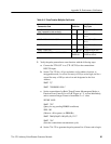
e. Set the 73A-270 to divide the 1 MHz external clock source by 10 (10 ms
resolution) and to set the pulse duration multiplier to 10 to generate a
square wave with a 200 ms period (5 kHz) with the following steps:
SET VX270
IBWRT "0S1R0A0M101L104L0C0B"
(Verify 5 kHz waveform)
f. Momentarily disconnect the SMB connector from the VX4790A and
check that the 5 kHz pulse pattern is no longer present on TTL OUT A.
2. Verify the Slow External Clock input with the following steps:
a. Turn the mainframe power off and remove the 73A-270. Return the
FAST EXTERNAL CLOCK switch to the C1 position and change the
SLOW EXTERNAL CLOCK switch to the ON (external) position.
Replace the 73A-270 and turn the mainframe power on. Reconnect the
coaxial cable to the TTL OUT A and the Arbitrary Waveform Generator
(clock source) to pins 5 and 4 (GND) of S1.
b. Program the 73A-270 to select the 200 kHz external clock and to set its
pulse duration multiplier to 20 to generate a 5 kHz square wave:
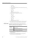
IBWRT "0S0R0A0M201L204L0C0B"
c. Set the clock source to provide a 200 kHz square wave.
SET VX4790
IBWRT "SETSQUARE 0 2.5 200000;1O;T"
(Verify 5 kHz)
(The fourth parameter is numeric one followed by alphabetic O.)
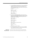
d. Momentarily disconnect the SMB connector from the VX4790A and
check that the 5 kHz pulse pattern is no longer present on TTL OUT A.
e. Using the oscilloscope probe, verify a 10 MHz clock signal on pin 17 of
S1 (4th pin up from bottom left).
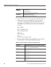
3. Verify the Transmission In Progress signal with the following steps:
a. Turn the mainframe power off and remove the 73A-270. Return the
SLOW EXTERNAL CLOCK switch to OFF and verify that the FAST
EXTERNAL switch is in the C1 position. Reinstall the 73A-270. and
turn on the mainframe power. Reconnect the coaxial cable to TTL OUT
A, and the external clock to S1 pins 5 and 4 (GND).


