


8
Setup & Installation
Initial Setup & Installation
INITIAL INSTALLATION
Note: Recommended Accessories
Rear wheel weights and front counterweights are
recommended. For operation on slopes greater than
15% (8.5°), front counterweights are required. Never
operate on slopes greater than 17.6% (10°).
Initial Installation Notes:
• The tiller idler pulley is wired to the tiller for
shipping purposes. USE CAUTION WHEN
CUTTING THE WIRE - THE IDLER ARM IS
UNDER SPRING TENSION.
• Remove the mower deck before beginning to
operate.
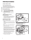
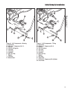
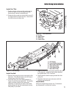
Replace Differential Lock Rod
(Early Models Only)
1. Locate the differential lock rod (A, B, Figure 1). If
the rod has no bends in it (B), replace it with the
rod included. If the rod has two bendds (A) it
does not need to be replaced.
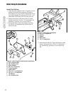
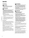
Modify Manual Lift Linkage
(Manual Lift Models Only)
1. Place the lift lever in the attachment-raised (back)
position.
2. Loosen the manual lift adjustment bolt (A, Figure
2) until the bolt can be slid out of the groove in the
bulkhead.
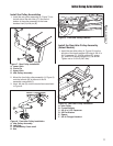
3. Remove the pin (A, Figure 3) securing the lift link
(D).
4. Remove the pivot capscrew (B) securing the lift
link (D) to the lift cam (J).
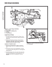
5. Check the front lock plate capscrew (L, Figure 4).
If the bolt is grade 5, replace with the 5/16-18 x 1
grade 8 bolt and whizlock nut provided.
6. Replace the lift link (D, Figure 3) with the new one
provided (D, Figure 4). Be sure to reinstall the lift
assist spring (not shown) in its original orientation.
7. Install the clevis pin (A, Figure 4) in the upper
tiller hole (K) in the lift cam, through the rear hole
in the lift link (D), through the spacer (I), and
secure with the hair pin clip (H).
8. Reinstall the manual lift adjustment bolt
(A, Figure 2) in the bulkhead.
C
C
B
A
Figure 1. Replace Differential Lock Rod
A. New Differential Lock Rod
B. Old Differential Lock Rod (Discard)
C. Hair Pin Clip and Washer
A
Figure 2. Manual Lift Adjustment Bolt
A. Adjustment Bolt