


7
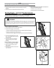
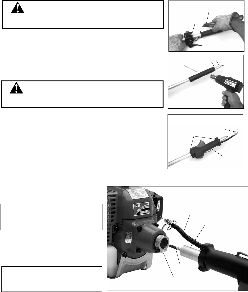
■ To avoid serious injury, grip the outer tube securely with one hand and cut
away from that hand when slitting the rubber throttle grip.
WARNING!
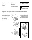
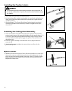
1. Place the T230 or PB230 outer tube assembly on a clean, at surface.
2. Loosen the three screws (A) that hold the throttle trigger assembly to the outer
tube.
3. Slide the trigger assembly down the tube, several inches away from the rubber
grip. Rotate the trigger assembly so it is at against the work surface.
4. With a utility knife or similar tool (B), slit the rubber grip lengthwise to release it
from the tube. Use gentle pressure to avoid scarring the outer tube.
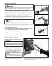
5. Remove the grip and slide the throttle trigger from the tube. Discard these
parts.
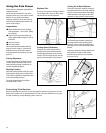
6. Clean surface of tube in grip area.
7. Make a mark on the tube, 2 inches from the upper end. Slide the heat shrink col-
lar (C) onto tube and align its upper end with the mark on the tube.
8. Using a heat gun or hair dryer, apply heat to the collar until it shrinks and forms
a snug t around the tube.
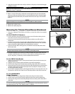
9. Slide the new interlock throttle grip assembly (D) onto the tube, and position
it over the collar. Make sure the switch is facing up, and that the throttle cable
and switch wires (E) are positioned toward the powerhead. Using a cross-head
screwdriver, tighten the grip's four clamp screws (F).
■ Failure to replace the standard throttle grip with the provided interlock throttle grip could
permit unintentional acceleration, which could cause serious injuries or death.
WARNING!
2-in.
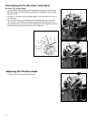
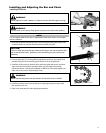
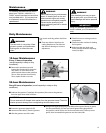
Powerhead Reinstallation
1. Place the powerhead on a clean, at surface in an
upright position.
2. Slide the outer tube (G) into the tube clamp (H)
until the outer tube bottoms. It should go in
about 1-1/2 in. (38 mm). If the outer tube stops
before bottoming, rotate it until you feel the in-
ner driveshaft (I) splines engage the powerhead.
Then push the outer tube all the way in.
CAUTION!
Do not remove the D-shaped shim washer! The
shim washer prevents damage from overtighten-
ing the tube clamp screw.
CAUTION!
Do not force the lower tube into the power-
head! Excessive force can damage the compo-
nents.
Installing Throttle Grip
A
B
C
D
E
F
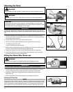
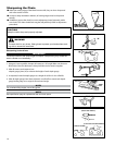
3. Position the outer tube so the stop switch is fac-
ing up and the throttle cable/wire assembly (J) is
on top.
4. Use the hex wrench to tighten the clamp screw rmly. Make sure the
D-shaped shim washer is in place.
J
G
I
H