


ASSEMBLY
CY84 03/08 Assembly Section 3-2
© 2008 Alamo Group Inc.
ASSEMBLY
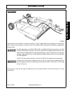
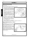
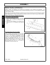
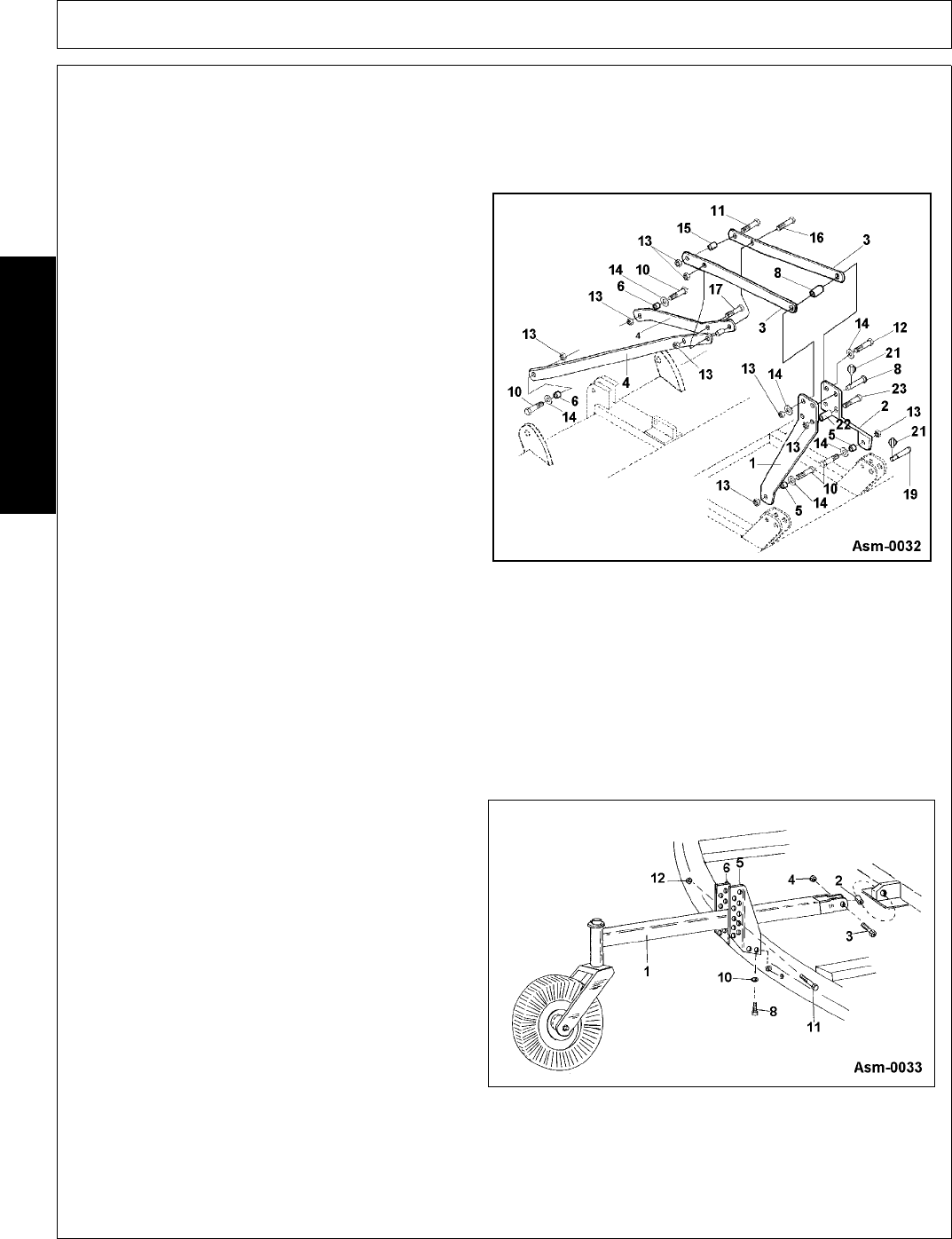
Optional A-Frame Assembly
(Figure Asm-0032)
To assemble the Mower’s A-Frame, follow the procedures listed below:
1. Insert bushing (5) into lower end of each A-
Frame half (1 & 2). Position each A-Frame half
so the large hole in the top is towards the trac-
tor. Install 3/4 x 2" bolt (10) with Flatwasher
(14) through bushing (5) in A-Frame half (1 & 2)
and rear hole in inside Main Frame lug. Install
locknut.
2. Install bushing (8) between braces (3) through
top rear hole of A-frame and insert bolt (12),
flatwasher (14) and locknut (13).
3. Install bushing (22) between A-Frame halves (1
& 2) and insert bolt (23) and locknut (13).
Install bushings (6) through Braces (4) and
install bolt 3/4 x 5 (10), flatwashers (14) and
locknut (13).
4. Attach Braces (3) to Braces (4) with bushings
(6), bolt 3/4 x 2-1/2 (16), and locknut (13).
Retain the rear of Braces (3) together with
bushing (15), bolt 3/4 x 2-1/2 (11) and locknut
(13). Attach braces (4) together with bolt 3/4 x
1-1/2 (17) and locknut (13).
5. Install Brace supports (4) to the rear lugs on the
Main Frame with bolts 3/4 x 2 (10), flatwashers (14), bushings (6) and locknuts (13).
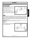
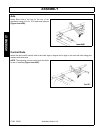
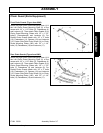
Single Tail Wheel Assembly - Lift-Type
(Figure Asm-0033)
Insert bushing (2) in lug centered behind gearbox.
Attach the tail wheel beam (1) to the lug on the
mower deck using bolt (3) and locknut (4).
Attach the brackets (5 & 6) to the main deck using
bolts (8), washer (9), & nuts (10). Note: Formed
leg with adjustment holes must point to rear and
should be on each side of tail wheel beam.
Install bolts (11) & nuts (12) on top and bottom of tail
wheel beam. Insert through pair of holes which will
give approximate desired cutting height. Tighten all
bolts per Torque Chart.