


OPERATION
CY84 03/08 Operation Section 4-16
© 2008 Alamo Group Inc.
OPERATION
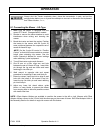
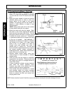
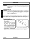
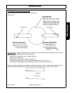
8.1 Driveline Length Check
When fitting the mower to the tractor, the telescoping driveline must be inspected to ensure that at its most
compressed position, the profiles do not “bottom out”, and when at its farthest extended position, there is
sufficient engagement between the profiles to operate safely. At its shortest length, there must be at least a 1”
clearance between each profile end and opposite profile universal joint. At its farthest operating extension, a
minimum profile engagement of 9” must be maintained.
Wh
en a
tt
ac
hi
ng
th
e
I
mp
l
emen
t
i
npu
t
d
r
i
ve
li
ne
t
o
th
e
T
rac
t
or
PTO
,
it
i
s
i
mpor
t
an
t
th
a
t
th
e
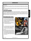
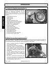
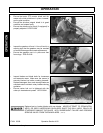
connecting yoke spring activated locking collar slides freely and the locking balls are seated
securely in the groove on the Tractor PTO shaft. A driveline not attached correctly to the
Tractor PTO shaft could come loose and result in personal injury and damage to the
Implement.
(S3PT-17)
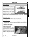
Before operating the Implement, check to make sure the Implement input driveline will not
bottom out or become disengaged. Bottoming out occurs when the inner shaft penetrates
the outer housing until the assembly becomes solid-it can shorten no more. Bottoming out
can cause serious damage to the Tractor PTO by pushing the PTO into the Tractor and
through the support bearings or downward onto the PTO shaft, breaking it off. A broken
driveline can cause personal injury.
(S3PT-18)
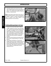
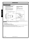
“B
o
tt
om
i
ng
O
u
t”
Ch
ec
k
P
roce
d
ure
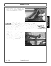
• Disconnect driveline from the tractor and slide
the profiles together until fully compressed.
• Place a mark on the inner shield 1/8” from the
end of the outer shield.
• Reattach the driveline to the PTO Shaft.
• Lift Type - With the PTO NOT TURNING, raise
and lower the mower and watch shaft
movement.
Pull Type - With the PTO NOT TURNING, drive
the tractor and mower through the sharpest turn
possible and watch shaft movement. With the
PTO NOT TURNING, drive the tractor and
mower through the most severe terrain condi-
tions expected and watch shaft movement.
• Raise the mower and watch the driveline as it
approaches the mark. If the distance between the mark and the end of the outer shield tube becomes less
than 2” at any point, contact your local dealer or tech service for proper directions. OPS-R-0004_B