


ASSEMBLY
FN10/FN15 NITRO 02/10 Assembly Section 3-6
© 2010 Alamo Group Inc.
ASSEMBLY
Many of the equipment components are HEAVY (60 lbs. or greater) and Special Lifting
Procedures are recommended. Use lifting assistance such as mechanical assistance, two
people, and proper lifting techniques when connecting or installing the driveshaft to reduce
the possibility of back injuries.
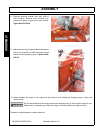
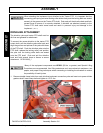
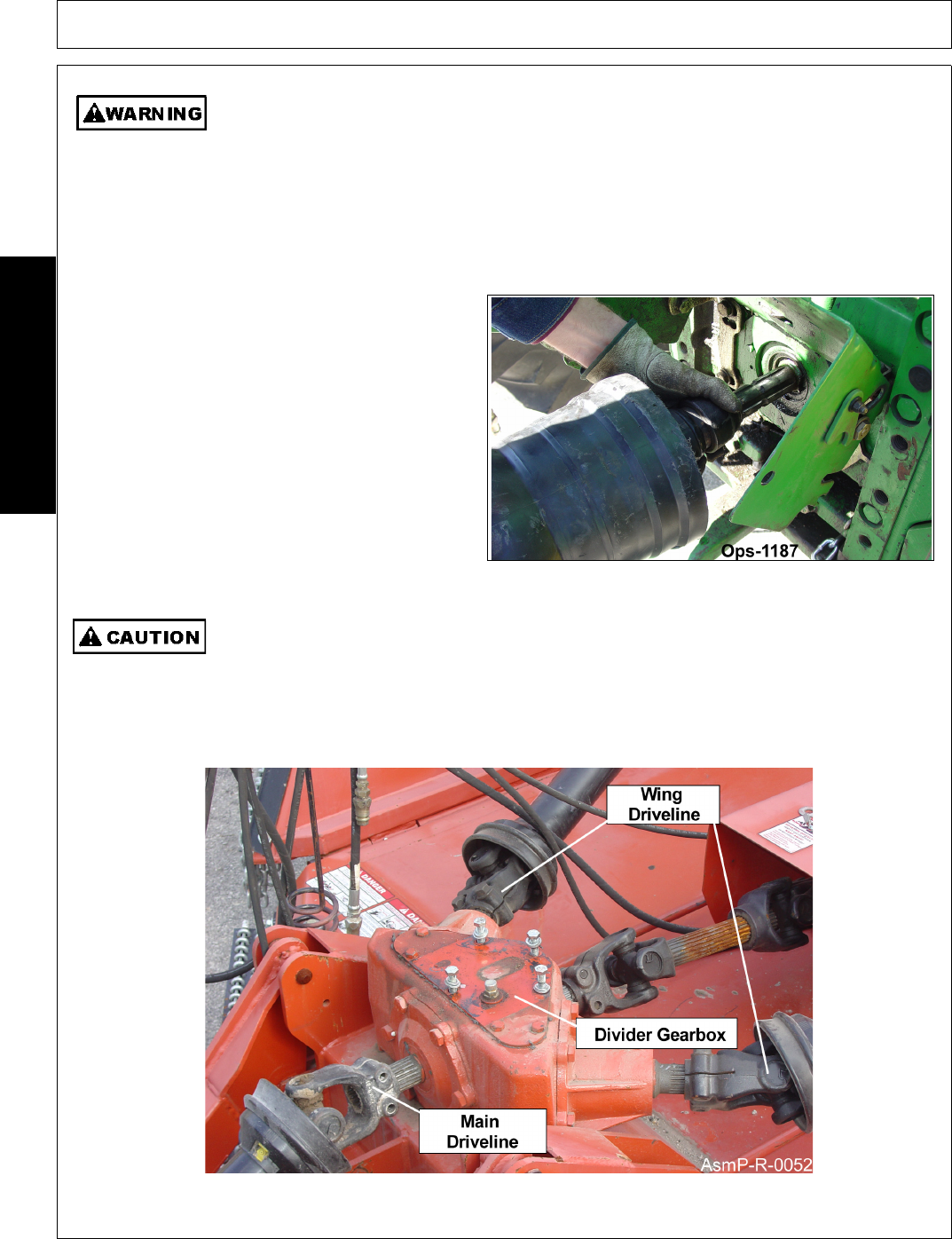
1. Remove double clamp bolts from main driveline implement connection yoke and insert onto power divider
gearbox shaft. Insert clamp bolt and tighten to 170 ft. lbs.
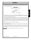
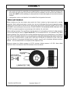
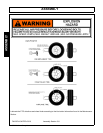
When attaching the Implement input driveline to the Tractor PTO, it is important that the
connecting yoke spring activated locking collar slides freely and the locking balls are seated
securely in the groove on the Tractor PTO shaft. Push and pull the driveline back and forth
several times to ensure it is securely attached. A driveline not attached correctly to the
Tractor PTO shaft could come loose and result in personal injury and damage to the
Implement.
(S3PT-17)
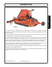
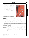
DRIVELINE ATTACHMENT
The driveline yoke and tractor PTO shaft must be
dirt free and greased for attachment.
To connect the mower driveline to the tractor PTO
output shaft, pull the driveline yoke collar back and
align the grooves and splines of the yoke with those
of the PTO shaft. Push the driveline yoke onto the
PTO shaft, release the locking collar, and position
the yoke until the locking collar balls are seated
onto the PTO shaft. Push and pull the driveline
back and forth several times to ensure a secure
attachment. OPS-R-0003_I