


TUBE CLEANING PROCEDURE
Establish a regular inspection schedule, frequency
depending on local water condition and severity of
service. Do not let the tubes clog up solidly. Clean out
deposits over 1/16" in thickness.
The heater may be cleaned from the return header
side, without breaking pipe connections. It is prefer-
able, however, to remove both headers for better visibil-
ity through the tubes and to be sure the ground-up lime
dust does not get into the system.
Note that you do not remove the top panel or the
heat exchanger, generally.
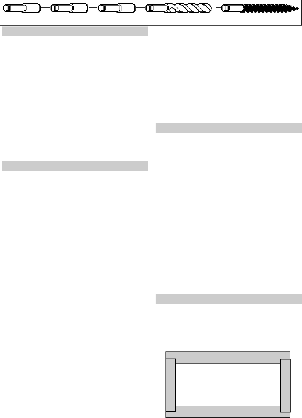
After reaming, mount the wire brush in place of the
auger and clean out debris remaining in the tubes.
Another method is to remove the heat exchanger,
ream tubes and immerse heat exchanger in non-inhib-
ited de-scale solvent for severe scale build-up.
TUBE REPLACEMENT PROCEDURE
On Raypak units, tube replacement may be ef-
fected without rolling, as a temporary means of repair,
providing there are two or more tubes rolled in to act as
stays on the left and right sides. The "O" rings should
provide a seal up to 125 PSI working pressure. Use 3/
8" heavy duty reversible drill motor or large to power the
tube roller. If a reversible drill is not available, after
rolling the tube in, remove the drill motor and wrench out
the roller. A tube roller is available from the factory.
Shut gas and power off to the unit, close the system
off and drain the heater. Remove the draft diverter.
Remove the access panel and jacket top. Lift flue
collector off. Remove "V" baffles over tube(s) to be
replaced. If no pipe unions have been provided, use the
header as a union, remove the flange nuts off the inlet-
outlet header, break gas connection and slide heater
away from piping to allow room to work. Pull wedge
clips out of control wells and remove sensing bulbs.
Remove flange nuts of the return header and remove
header. Lift heat exchanger straight up and inspect "O"
ring seals at this time. Unless severed they are reus-
able. The tube may be cut out the a hacksaw or hammer
and chisel adjacent to both tube sheets, leaving studs
in the tube sheets. Then proceed to collapse studs in
the tube sheets with a chisel or screwdriver. Use
caution not to cut into the tube sheet. Replacement
tubes will have the fins stripped off longer on one end.
The long end is inserted into the opening of the tube
sheet first; then the short end is fitted through the
opposite tube sheet. If the tube ends become dented or
bent, straighten at least (4) inches back from the tube
and by means of a tapered punch.
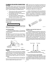
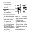
Insert tube roller into tube opening up to stop
against tube, then push center rod in until roller is tight.
Be careful to keep replacement tube squared up 1/8"
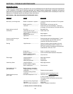
Extension Pieces (2) Auger with Carbide Tip Wire Brush
21
outside each tube sheet. A loose tube will sometimes
pull toward the roller. Attach drill motor to tube roller,
holding it straight and level. Proceed to expand tube
until the tool begins to grab. At this point, 1/2" to 1"
should be exposed on the tool shank. Reverse drill
motor or wrench out by hand. Care should be exercised
to avoid applying excessive torque during rolling opera-
tion and to avoid thinning out any part of the tube wall
excessively over .015". Use same procedure at the
opposite end of the tube.
Apply line pressure test, and re-roll, if necessary
before re-assembly of the heater.
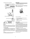
DESOOTING PROCEDURE
CAUTION:
SOOT IS COMBUSTIBLE. EXERCISE
EXTREME CARE. NEVER USE A WIRE BRUSH.
Soot can clog areas between fins and cause even-
tual tube failure. Any sign of soot at the base of the
burners or around the outer jacket indicates a need for
cleaning.
1. Disconnect top portion of unit. (See heat
exchanger
removal procedure steps 1 through 6).
2. Remove burner tray (See burner tray removal
procedure.)
3. Take a garden hose and wash heat exchanger,
making sure soot is removed completely from be-
tween fins. Avoid excessive water against refrac-
tory.
NOTE:
In extreme cases it may be necessary to re-
move the heat exchanger completely for cleaning. The
simplest method is steam cleaning at the local car
wash. DO NOT WIRE BRUSH.
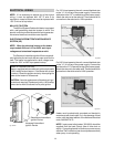
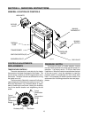
COMBUSTION CHAMBER REMOVAL
1. Remove heat exchanger (See heat exchanger
removal procedure).
2. Lift up and remove front and rear refractory shield.
3. Remove refractory panels.
4. Reverse above procedure to re-install.
Fig . # 8155.0s
Refactory Panel Top View
Fig. # 8154.0