


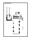
PLUMBING FOR WATER CONNECTIONS
LOCATION
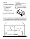
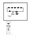
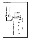
The VERSA heater requires water flow and positive
pressure to fire and operate properly. It must therefore be
installed downstream of the discharge side of the filter
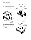
pump. A typical installation is plumbed as follows:
1. The inlet side of the filter is plumbed directly to
the discharge side of the filter pump;
2. The outlet side of the filter is then plumbed to
the inlet of the heater; and
3. The outlet of the heater is plumbed to the
return line to the pool or spa. The pump, filter
and heater are thus plumbed in series.
Plumbing from the heater back to the pool must not have
any valves or restriction that could prevent flow when the
pump is operating. To do so will void the warranty.
FLOW RATES
MIN.GPM: 20, MAX.GPM: 115*
*When flow rates exceed 115 GPM an external auxiliary
bypass valve is required. See External auxiliary bypass
valve section for details.
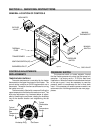
CAST IRON HEADER
The inlet/outlet header accepts a 1-1/2" pipe thread.
The header will accept either copper and galvanized pipe
or CPVC adapters.
CAUTION: Never install PVC directly in header flanges.
The initial connection must be made with a higher
temperature material such as CPVC or Copper. PVC
may be utilized immediately after the initial connection.
13
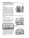
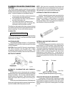
INLET/OUTLET HEADER
AUTOMATIC CHLORINATORS AND CHEMICAL
FEEDERS
All chemicals must be introduced and completely
diluted into the pool or spa water before being circulated
through the heater. Do not place chlorine tablets or
bromine sticks in the skimmer. High chemical concen-
trations will result when the pump is not running (i.e.
overnight).
Chlorinators must feed downstream of the heater and
have an anti-siphoning device to prevent chemical back-
up into the heater when the pump is shut off.
NOTE: High chemical concentration from feeders and
chlorinators that are out of adjustment will cause very
rapid corrosion to the heat exchanger in the heaters.
Such damage is not covered under the warranty.
1 1/2" NPT
INLET/ OUTLET
CONNECTIONS
IN/OUT
HEADER
Fig. # 9249
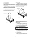
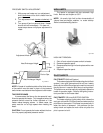
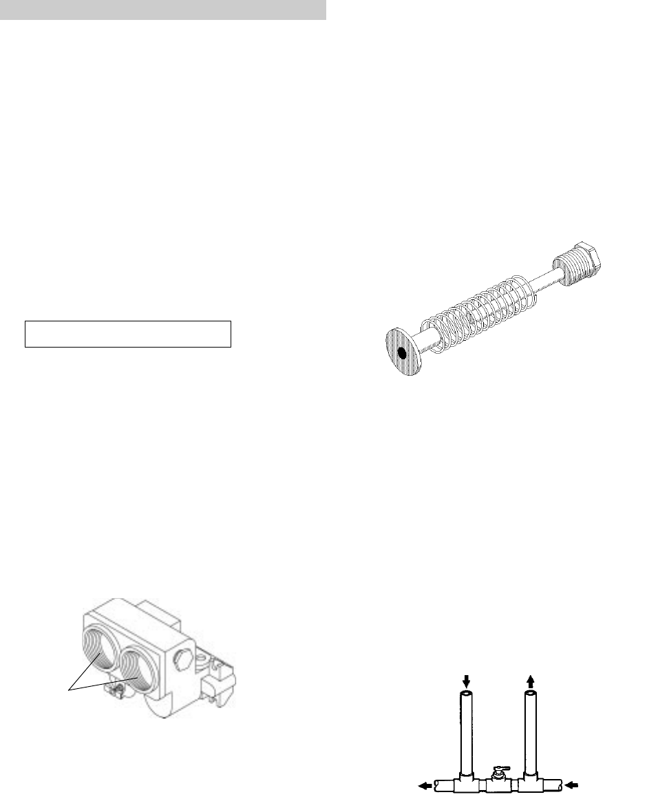
INTERNAL AUTOMATIC BY-PASS VALVE
A built-in automatic by-pass valve is provided in the
in/out header. The internal by-pass valve automatically
responds to changes in water pressure in the piping
system. Proper amount of water flow is maintained
through the heater under varying pressures dictated by
the conditions of the pump and filter.
Fig. # 8078.0
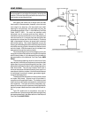
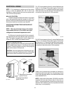
EXTERNAL AUXILIARY BYPASS VALVE
(Where required)
An auxiliary bypass valve should be used when flow
rates exceed 115 GPM (usually a high performance
pump size larger than 2 HP will exceed this flow rate).
This valve is required to complement the function of the
automatic bypass valve, particularly when starting the
heater in winter or early spring when the spa or pool
temperature is down below 55°F. It also serves to
eliminate needless pressure drop through the heater and
accompanying reduction in the flow rate to the spa jets,
etcetera.
From Heater To Heater
To Pool From Pool
Auxiliary Bypass Valve (do not use gate valve)
Fig. # 8150.
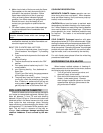
AUXILIARY BYPASS VALVE ADJUSTMENT
To set bypass: With clean filter, adjustment is made
by feeling the inlet and outlet pipes at the heater. Outlet
pipes should be slightly warmer than inlet and comfort-
able to the touch. If pipe is hot, close bypass; if cold, open
bypass.